Kraków 2009-07-14
167c Section 21 July 1959.
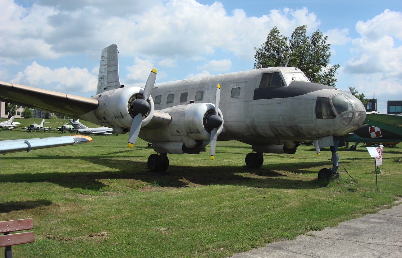
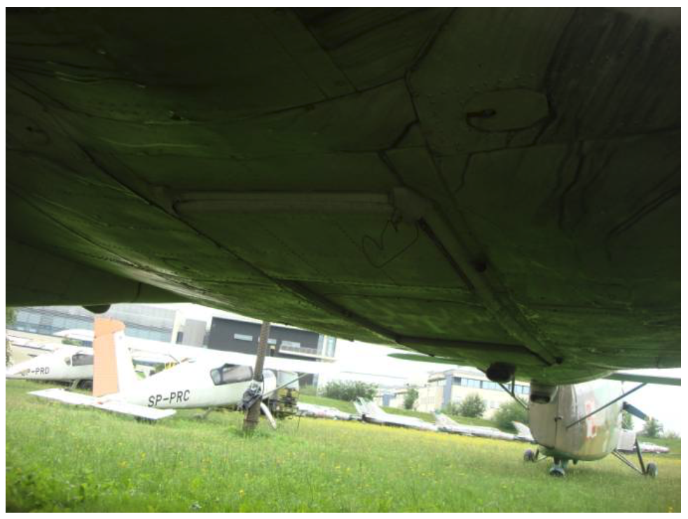
WSK-Okęcie OKL MD-12. Poland
Passenger aircraft, photogrammetric.
Construction

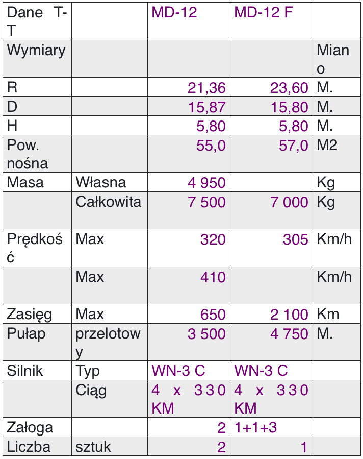
MD-12 Design
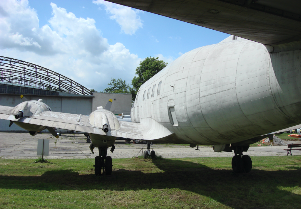
The MD-12 is a passenger aircraft. Capable of carrying 20 passengers with a crew of only two. Designed for short routes. Capable of flying under IFR conditions and at night. A low-wing monoplane with a conventional layout. Four-engine. All-metal construction.
The MD-12 is the only Polish aircraft with a four-engine engine.
The wing is straight, with a trapezoidal planform. However, it has a significant 5-degree sweep. The NACA 230 wing profile, which was very popular at the time, was adopted. It is practically symmetrical. Only the wing’s nose is more curved downward. A wing with this profile has a very good lift coefficient, much better than the previously used and newly launched laminar profile. However, this profile had a significant drawback. The jet separation occurred suddenly, without any warning, with a significant drop in lift coefficient. This meant the aircraft had no warning of the stall and plummeted.
The wing was technologically divided into outer sections and a center wing with engine nacelles. The construction technology for both sections was completely different. The wing ribs were quite strong and rigid. Corrugated sheet metal replaced numerous riveted angles. The wing was equipped with ailerons and flaps.
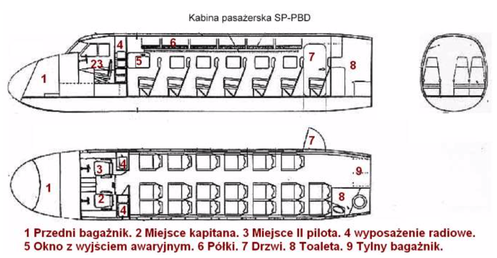
The fuselage was oval in cross-section, higher than it was wide, providing ample headroom. The fuselage begins with a nose that accommodated the front luggage compartment. The Lockheed L-10 Electra and Lockheed L-14 Super Electra aircraft had a similar design. The cockpit is ergonomic, with good visibility through the windows. The cockpit glazing consists of six windows. All windows are equipped with flat glass. The two largest ones in front of the pilots were equipped with windshield wipers and a heating and ventilation system. The front side windows were openable. The pilots’ and passengers’ cockpits are not pressurized, but are heated and ventilated. The pilots’ cockpit is separated from the passenger cabin by a partition with a door offset slightly to the right, due to the seating arrangement.
The cabin was constructed in accordance with applicable regulations. The main entrance was located aft on the starboard side. Two emergency exits with windows are much larger than the window itself, as required by regulations. However, as it turned out, the regulations did not specify that an emergency exit should be located above the wing. It is assumed that this feature would have been improved during series production. Fortunately, no one ever had to use the emergency exit. The passenger cabin was equipped with the main door located aft on the starboard side and windows; six on the starboard side and seven on the port side. Their arrangement coincided with the individual rows of seats, so that each passenger seated at the starboard side had a window. The windows were rectangular in outline and had curtains. The passenger seats were individual, upholstered, with high headrests and small earpieces. Concave headrests made it easy to take a short nap without worrying about the sleeper’s head wandering onto the passenger next to them. The backrests weren’t adjustable, but they were equipped with armrests. Each passenger had exceptional space by today’s standards. If a super-economy version were built, the cabin could accommodate six more seats. Open shelves for hand luggage were located on both sides of the side, above the seats. A fully functional lavatory with a toilet and sink was located at the rear of the fuselage. By today’s standards, the lavatory was large. There would also have been room for a stewardess and a buffet.
The empennage is classic, with rudders and stabilizers separated into simple, trapezoidal contours. The horizontal empennage, like the wings, has a 5-degree sweep. The empennage is constructed using technology similar to the outer wing sections. The empennage ribs are made of thin sheet metal, 0.5 mm thick.
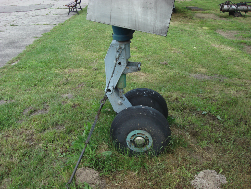
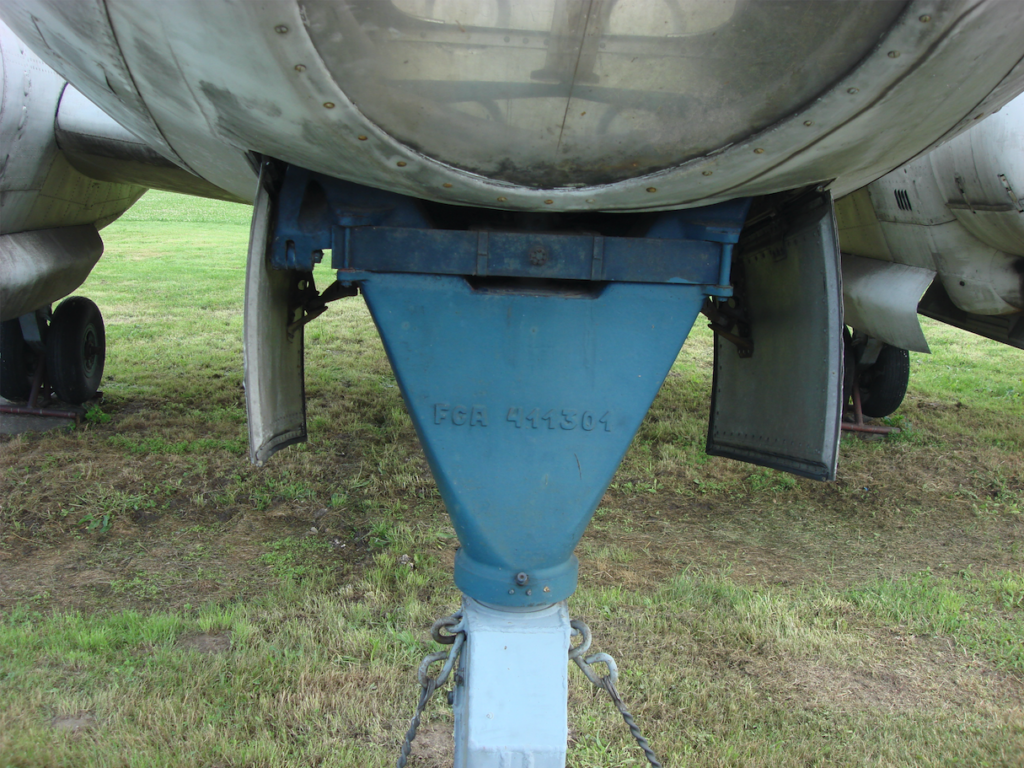
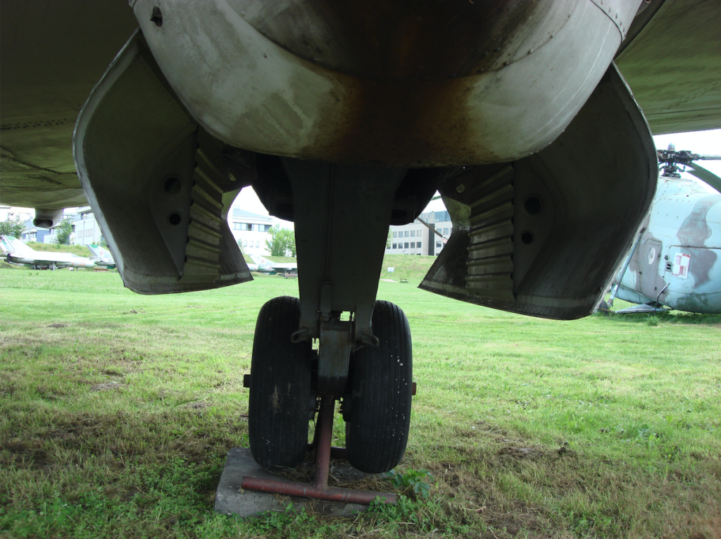
The landing gear is classic, three-strut, fully retractable, with all wheels twin. The front wheels retract rearward. The landing gear compartment is closed by four flaps, with the rear flaps only open during retraction or extension, reducing the possibility of contamination of the landing gear compartment. The main landing gear is supported by the wings and retracts forward into extended engine nacelles.
MD-12 Powerplant.
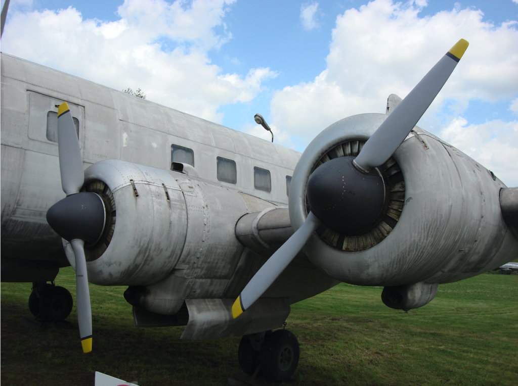
After numerous trials and tribulations, the powerplant selected for the MD-12 consisted of four WN-3C engines, producing 4 x 330 hp. This engine powered the TS-8 Bies aircraft. In addition to the engine, the propeller and cowlings were also adopted. Engineer Wiktor Narkiewicz designed the engine, modeling it on the American Jacobs engine used in twin-engine Cessna Bocat aircraft.
The WN-3 C is a 7-cylinder radial engine, air-cooled. Takeoff power is 4 x 330 hp (244 kW), and continuous power is 283 hp (208 kW). The engine has no compressor or reduction gear. The lack of a compressor causes a loss of power with increasing altitude. However, the absence of a reduction gear results in a high-speed propeller. The engine cowling is an annular, long-chord NACA type. The air intake is equipped with a shutter, manually adjustable from the cockpit, allowing for optimal engine operating temperature. The engine is started by compressed air. A flat-scroll oil cooler is located under the front of the cowling, in front of the cylinders. The exhaust pipes are equipped with a system for heating the cabin and de-icing the wings.
The propeller, mounted on the engine shaft, was a two-blade, wooden, adjustable propeller, of the WR-1 type, with a diameter of 2.2 m. It is relatively noisy during operation.
The WN-3 engines on the MD-12 aircraft never failed. If there were any faults, they were limited to the ancillary equipment.
The aircraft reached a cruising altitude of 3,500 m, but the maximum altitude was unattainable due to the lack of a pressurized cabin.
The aircraft was equipped with a radio station, radio compass, and radio altimeter. However, the problem was that these devices were very heavy, even for the time, weighing approximately 200 kg. If the communist authorities were interested in this aircraft, nothing prevented them from developing and building new, more accurate, and lighter devices or purchasing them from the West.
Design of the MD-12 F
The aircraft underwent many significant changes. First and foremost, its intended purpose was changed. It is a purely photogrammetric aircraft. The wing was lengthened to a span of 23.60 m by adding 1.12 m wingtips with a different wingtip shape. The flaps and ailerons remained unchanged. These changes increased the wing’s lifting area, allowing the aircraft to reach higher altitudes.
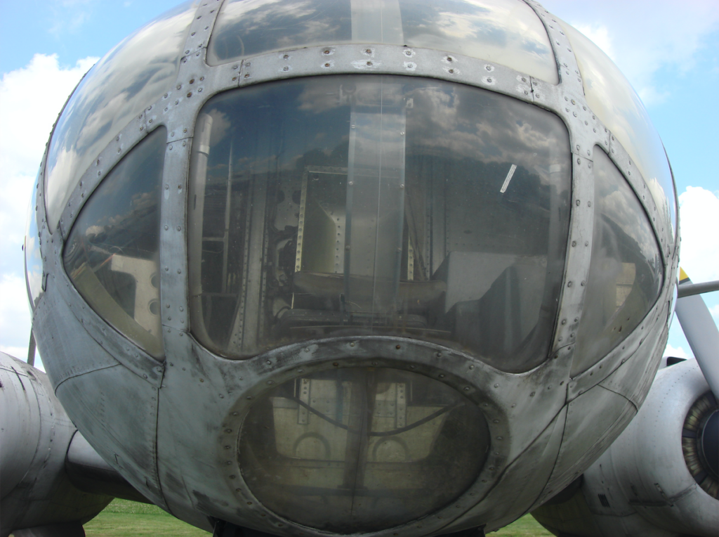
The fuselage underwent significant changes. A glass-enclosed navigator’s cabin appeared in the nose, accessed by removing the co-pilot’s seat. The nose cockpit received nine windows with convex organic glass panes. Only the lower window was equipped with flat glass. The navigator sits in a centrally located seat, with the control panel to the right.
The passenger cabin was transformed into a film and photography room, with four camera stations installed, manufactured by Carl Zeiss in Jena, East Germany. Two stations were for vertical shots and two stations for oblique shots, left and right. Special openings have been made for these stations, which when not in use are covered with metal covers that are only moved when the devices are in operation.
Written by Karol Placha Hetman