Kraków 2014-09-24
Outline of the history of navigation.
Automatic landing systems.
Landing systems NDB, USL, RSP, ILS are discussed in other chapters. In this section, we present the historical events that influenced the landing technique.
Prologue.
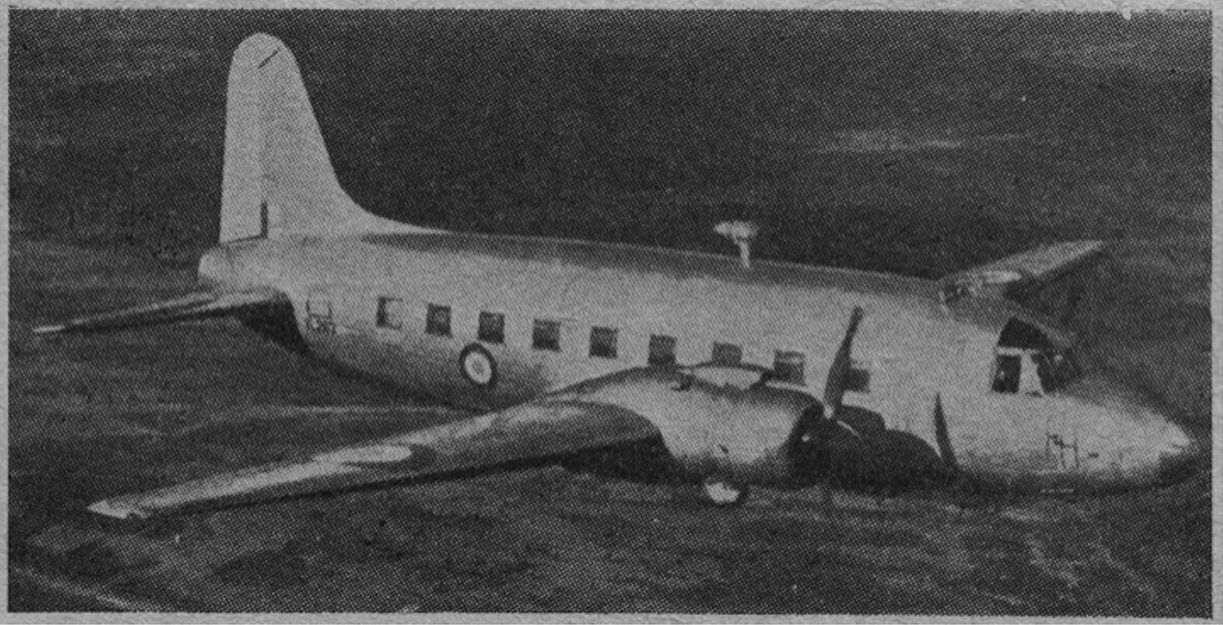
In the 1940s, a US Post Office survey showed that 76% of forced landings were due to bad weather. Therefore, extensive efforts have been made in the US and UK to develop a blind landing system that would enable landing at night and in bad weather. The governments of both countries were involved in the activities. It didn’t matter whether the plane was military or civilian. The main research work lasted from 1949 to 1965. The first result of the work was the development of lighting systems extending from the runway threshold for a length of 1 mile in both directions. The system turned out to be good, but left me unsatisfied. The more so as not all airports had a place to develop such lights. Once again, attention was paid to radio systems. Researchers concluded that the system must be based on ground equipment and mounted on the aircraft. All aircraft would have to be equipped with a sensor for signal reception, a super-precise altimeter, and a reliable autopilot. The barometric altimeters used at that time were inaccurate. That is why radio altimeters were developed. Such a device allows for precise determination of the flight altitude above the ground. The accuracy was 1-2 m. The track radio signal was emitted from a device installed at the end of the runway. The first automatic landing in the UK was made by Lt. Noel Adams on a test plane Vickers Varsity, on 7/3/1950. For the system to be widely introduced, it was necessary to prove that it is safe. The standard demanded; 1 accident in 10,000,000 landings. A long-standing discussion flared up. In addition, the airport where the tests were carried out was completely closed due to the systematic fog. Tests moved to Heathrow Airport.
The Vickers Varsity plane is a British machine designed for training of the Royal Air Force crews. The first prototype flight was made on July 17, 1949, and in 1951, the aircraft entered service with the RAF, where it served for 25 years. The Vickers Varsity is a metal low wing wing with two piston engines. Mainly the bomber crews trained in navigation and bombardment (bomb drop targeting) on the plane. The crews of series V bombers were trained on these airplanes; Valiant, Vulcan, Victor.
Basic Vickers Varsity data; dimensions span 27.20 m, length 19.10 m, height 7.32 m, empty weight 11,350 kg, total, 16,550 kg, fuel 2,800 kg, max speed 470 km / h, cruising speed 420 km / h, ceiling 6,700 m, range 2,000 km. Power unit; two Herkules 230 piston engines with 2 x 1,975 HP. The transport and landing version takes 36 paratroopers on board.
The landing aid system has evolved. Eventually, in 1964, the system was adopted for commercial aviation. On November 4, 1964, the first commercial landing with the use of the ILS system in the UK (Heathrow airport) took place with a visibility of only 40 m.
USA 20-years of the 20th century.
In the second half of the 20-years of the twentieth century, radio devices were already so developed that one could think of using Otto Scheller’s patent from 1907, for the principle of routing equal radio signals along the lines. In 1921, American engineers F.H. Engel and F.W. Dunmore developed a Low Frequency Beacon (or LF-RNG – Low Frequency Radio Range) route beacon. Four antennas transmitted directional Morse characters A (.-) and N (-.), Forming two or four narrow zones of overlapping characters with equal loudness. The pilot controlled so that a continuous signal could be heard in the headphones of an ordinary mid-wave receiver.
Dunmore’s subsequent work on the DLB (Dunmore Landing Beam) and BSS (Bureau of Standards System) systems led to a Low Visibility Landing Approach System: the system was to determine the landing course, angle of descent and distance to touchdown. These systems determined the landing direction using the method of equal signals from a transmitter with two antennas. 65 and 86.7 Hz tone modulation was used instead of Morse code characters. On board the plane, the pilot had a simple vibration frequency meter acting as an indicator. The anchors of the two electromagnets connected to the outputs of the receivers were of different lengths; one resonated at 65 Hz, the other at 86.7 Hz. Along the optimal direction of the approach, the vibration amplitude of the anchors was equal.
The more advanced BSS system had a set of devices defining the glide path. However, the reflection of waves from the ground surface meant that the line of equal signals obtained in practice was a curve that was difficult to interpret. To improve accuracy, an additional terrestrial non-directional beacon was used as a marker. It sent a 40 Hz signal. In addition, the reading on board the aircraft was made with a precise ammeter, which had to be calibrated each time.
The BSS (Bureau of Standards System) should be considered as the precursor of the ILS system. The system tests were positive, but their practical application was extremely difficult. Therefore, the BSS and DBL systems did not leave the research area. Cost and effect were not comparable.
As a result, a simple system was used based on a radio-finder mounted on the take-off area. The plane, after passing over the radio finder, kept the course opposite to the landing direction for a specified period of time. Then he made a 180-degree turn and approached the landing, correcting the direction according to the indications of the beacon operator. The pilot determined the glide path according to the clock, altimeter and wind.
Another system of this type was the approach by two medium wave beacons LFB or NDB (200 to 600 kHz). The direction of approach was indicated by an on-board radio finder, called a radio semi-compass. In 1930, Captain Hagenberger of the US Air Force built an automatic radiocompass that automatically and continuously indicates the direction of the beacon. For the two beacon approach, two sets of radio compass on board came in handy. This method is still used today as an approach for two NDBs.
The Germanic system of Lorenz and Knickebein.
It is commonly believed that the first successful radio landing approach system was developed by the Germanic scientist Ernst Kramar in 1932. The system was even called Lorenz. Several similar experimental systems were developed during this time. A novelty in the Lorenz system was the use of short wave (30-40 MHz). The short wave increased the accuracy of the guidance. In addition, the meter wave band was little used in the 30 years, so there were no problems with interfering with the waves used for radio communication between the flight crew and the ground staff. Besides, the system was not revolutionary. He used the principle of equal signals and modulation used in telegraphy. When turned to the right, the signals were long, i.e. dashes, and when turned to the left, the signals were short, i.e. dots. In the axis, the signal should be continuous, because the dots were between the dashes. The range of the Lorenz system was approximately 48 km and was fully satisfactory. The Lorenz system on the approach, in the runway axis, had two markers that worked at 38 MHz. The next one was making lines in a low tone, the closer one was making dots in a high tone. The waves were emitted with the help of electron tubes.
The system test took place in the fall of 1933 at Tempelhof Airport. The Junkers 52 / 3m aircraft was used for the tests. The tests were successful, and as the system was offered for sale, it was installed at around 40 airports in Europe as early as 1936. The Lorenz system was also purchased by the Republic of Poland and installed in 1937 at the Okęcie airport (approach direction 310 degrees, and the beacon was standing on the side of Krakowska Avenue) and in Vilnius at Porubanek airport. In 1938, the system appeared at the airport in Gdańsk-Wrzeszcz.
In Germanania, the Lorenz system evolved towards typically military applications. The Knickebein system appeared, which was used to guide bombers. The Germans used it in the first period of World War II in bomb attacks on GB. In short, the Knickebein system was an evolution of the Lorenz system with more powerful transmitters and much larger antennas. The basis of the Knickebein system were two transmitters emitting Morse code signals (dots and dashes) on VHF waves at a frequency of about 30 MHz (usually 30 or 31.5 MHz). Range up to 300 km. On the other hand, the bomber planes had receivers with a much higher sensitivity than in the Lorenz system. The plane was following the signal of the transmitter that was aimed at the target. If the plane was following the correct course, the pilot heard a continuous signal in the headphones. The width of this signal was about 365 m. The departure from the course was manifested by an increased intensity of lines or dots. Above the target, the signal beam along which the bomber was flying crossed the signal of a second, different transmitter. This signal was picked up by another receiver, and it was heard by the bombardier. It was a signal for him to throw bombs. The transmitters were placed on slopes and masts so that their height above the ground was at least 30 m, because it ensured a sufficient range. The first transmitters were set up in Germany. After the occupation of France, they were installed closer to the British Isles. However, the UK started using jamming devices and the efficiency of the system decreased drastically.
British SBA system.
In the UK, the SBA (Standard Beam Approach) system was developed according to the Lorenz system scheme. The serial production was started by Standard Telephones And Cables (STC). The system worked on six channels of the 35-40 MHz range. A variety with smooth regulation quickly appeared.
At the beginning of 1940, yet another system for assisting landing in bad weather was developed in the UK. The system was called Blind Approach Beacon System or Beam Approach Beacon System for short BABS. The system was developed and modified, but in the field of research.
American ITT system.
In the USA, according to the Lorenz system scheme, the landing system was developed and built by International Telephones and Telegraph (ITT). The localization beacon operated at 110 MHz and the path beacon was 94 MHz. Through careful development of the receiver’s antenna systems and filters, a straight glide path beam up to a height of 200 m was obtained. A special cross-shaped indicator, popular to this day, was developed for airplanes. Thanks to it, the pilot did not have to listen to the signals emitted by the headphones all the time, which was not the most convenient. This indicator was taken over to the ILS on-board sets. A third, middle approach marker has been added to the ITT system.
Written by Karol Placha Hetman


