
Mielec 2008-09-20
History of the TS-16 Grot.
198b Section 1965. PZL TS-16 Grot.
The PZL TS-16 Grot was intended to be a supersonic trainer and attack/combat aircraft. The aircraft was intended for the Polish Army, replacing the PZL TS-11 Iskra. However, the aircraft was never built and remained in draft form.
It’s very difficult to write about an aircraft that didn’t fly, or even a prototype. However, it’s worth writing about, as it demonstrates the aspirations of Polish designers and the capabilities of Polish industry at the turn of the 1950s and 1960s. Crucially, the aircraft had a great chance of becoming a real flying machine, not just a paper dream. While writing this chapter, we gathered all possible information about it, which is presented below.
Design assumptions.
By the end of the 1950s, it was certain that supersonic aircraft would become a permanent fixture in military aviation, including Polish aviation. (At that time, talks were already underway with the Russians about acquiring MiG-19 fighters.) During this period, supersonic flights were considered, and rightly so, extremely difficult and dangerous. Therefore, they required special training. It was unthinkable to graduate from flight school with a pilot who had never completed a single supersonic flight and had only learned the art in a combat unit.
Whether our authorities followed the path set by the American Air Force or whether it was pure coincidence is difficult to determine today. One thing is certain: in 1955, the Northrop T-38 Talon supersonic trainer aircraft was developed in the United States. It first flew in 1959, approximately 900 units were built, and in 2008, there were still no plans to abandon it. Furthermore, the T-38 evolved into the F-5 fighter in numerous variants. It is unlikely that the Polish design will become such a giant, but on a local scale, it is possible.
Around 1958, the Air Force Command developed a design for a supersonic trainer aircraft for student pilots in their final year of training, who were already significantly advanced in subsonic aircraft. We can almost certainly be certain that these design for the aircraft were preliminary, not definitive. Why? Because only two years earlier (1956), a design for the TS-11 Iskra aircraft had been developed, which had not yet taken to the air. Since maximum speed was a decisive requirement for the new design, the design for the aircraft was set at Mach 1.3, while for the TS-11, it was set at Mach 0.8.
What else was included in the design for the aircraft? Certainly, the type of propulsion system. The decision was, of course, to go with a Polish-designed engine. The engines used in Lim-class fighters were unsuitable due to their excessively large cross-sections. The correct approach was to use the engine developed for the TS-11 aircraft. However, to achieve adequate power, it had to be equipped with an afterburner and two units installed. Logically, the engine for the new aircraft was designated SO-2. Incidentally, the SO-1 engine was also still in development. This powerplant philosophy was very consistent. The aircraft takes off without afterburners, using them only for short supersonic cruises. This minimizes fuel consumption while simultaneously meeting the basic requirement. It’s impossible not to mention the significant reduction in R&D costs and the future operation of various aircraft with nearly identical engines.
The new design had an upper gross weight limit of 5,000 kg, as a heavier aircraft would require a more powerful propulsion system. The WWTT also specified that the aircraft would operate from ground airfields. The aircraft’s capabilities for certain combat missions were also discussed.
Initial work on the TS-16 Grot.
Who was to develop this aircraft? The only office capable of handling this task was that of Professor Tadeusz Sołtyk, Master of Science in Engineering. In 1958, a group of designers was separated from his team and tasked with designing an aircraft designated the TS-16 Grot. Naturally, TS stands for Tadeusz Sołtyk.
Since the aircraft was intended to perform some combat missions, it was logical from the outset to develop two versions, a single- and a two-seater. The lack of a second crew member freed up additional space and weight, which could be used to carry a larger weapons load. The single-seat version was designated TS-11A and designated as a fighter-attack aircraft, while the two-seat version, TS-11B, was designated as a trainer. Combat missions included engaging moving and stationary ground targets with a cannon(s), missiles, and bombs. The training tasks included training pilots in their final year of flight school and flight training for crews of supersonic combat aircraft. Since versions A and B were to differ as little as possible, the A version’s radio (and other) equipment was planned to be placed in the rear cockpit, while more powerful armament was mounted in the nose. Furthermore, the glazing of both versions would be identical.
To minimize the risk of program failure, it was necessary to rely on proven solutions. Therefore, the aircraft had to be designed in a classic layout: a high-wing or medium-wing aircraft. The wings were swept, with a leading edge sweep of approximately 40 degrees to achieve low drag while maintaining sufficient lift. The tailplane was designed in a classic layout, also swept, with horizontal slab-based tailplanes. The fuselage was as narrow as possible, with the powerplant located in the rear section of the fuselage. During the design process, it was decided to apply the so-called “area rule,” known since 1953. This is crucial for achieving supersonic speeds with relatively low propulsion power.
To reduce R&D costs, it was necessary to maximize the use of existing solutions and components used in Poland and the Council for Mutual Economic Assistance (CMEA) countries.
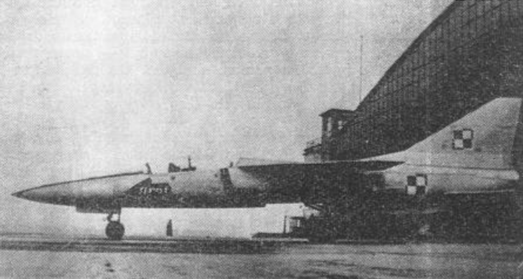
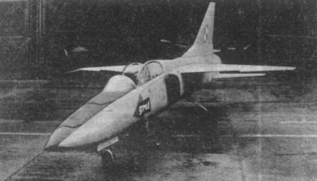
Work proceeded quickly, and the TS-16 study was completed in December 1959, allowing construction of a full-size mockup to begin.
TS-16 Grot Study.
The wing. It was given a very modern shape. It is bi-trapezoidal. It closely resembles the wing of the then-famous American F-101 fighter, although it is even more modern, as it has a leading edge sweep. The leading edge sweep performs the same function as an aerodynamic guide. The wing has a section near the fuselage and a section outboard. The angle of attack is 40 or 45 degrees. The trailing edge near the fuselage is minus 10 degrees, where the flaps are located. The outboard section is plus 10 degrees, where the flaps are also located. The wings have no ailerons. A laminar, symmetrical airfoil is used. From the leading edge step, the nose curves downward.
The semi-monocoque fuselage is shaped according to the area rule. Behind the cockpit and in front of the wings are side air intakes for the engines. They are optimized for operation in the Mach 1 speed range. They are non-adjustable. Their cross-section is nearly rectangular, and the nose is sloping with a forward upper edge. The edges are relatively sharp. Each air intake powers a single engine. The engines are located in the rear of the fuselage, side by side. Due to the small size of the engines, the shape of the fuselage in its rear part is as closely aligned as possible with the area rule. The engine exhaust nozzles are slightly offset from each other and additionally separated by a specially shaped fin, which forms the basis of the vertical tail. This nozzle arrangement minimizes the influence of one engine gas stream on the other. This is important due to the low (limiting) thrust of the engines. This fin also serves as a container for the braking parachute.
The vertical tail is a classic design, divided into a rudder and stabilizer. The horizontal, plate-shaped tailplanes are controlled like elevons, acting as elevators and ailerons.
The three-wheel undercarriage was supported and fully retracted into the fuselage. Both the nose and main wheels were forward. The main landing gear was designed so that, in the retracted position, one wheel overlapped the other. This was a pioneering solution, practically never replicated. It minimized the volume of the main landing gear bay, which is practically single.
Equipment. At that time, the avionics were not very extensive and consisted of basic flight and navigation instruments. Among the modern devices, the following should be mentioned: a radio rangefinder and a radar gunsight. To streamline the training process, a damage simulator was planned. This system was to be controlled from the second cockpit and was intended to interfere with the instruments in the first cockpit to develop proper piloting habits. A 23 mm cannon was planned for armament. The use of under-fuselage and under-wing nodes for carrying weapons or additional fuel tanks was considered. However, no work was undertaken in this direction.
Alternative design.
At that time, the WSK PZL-Mielec design office developed a comparative study of the PZL M-16 STN aircraft. It was a delta-shaped aircraft without horizontal tail. The powerplant, similar to the TS-16, consisted of two SO-2 engines.
Different TS-16 powerplant.
As work on the SO-1 engine, and consequently the SO-2 engine, dragged on, another solution was sought. Furthermore, the actual properties of the SO-2 engine were unknown. At that time, the Polish Army received a batch of MiG-19 fighters powered by two RD-9B engines. It must be admitted that the RD-9B engine was a refined and extremely successful design. It has a small diameter, is lightweight, and has a very favorable thrust-to-weight ratio. In the 1950s, it was the primary powerplant of Russian experimental fighters of the E-2, E-4, and E-5 series. Designed by S. Tumański, it had a thrust of 1 x 2,550 kG (1 x 25.5 kN), and with afterburner, 1 x 3,237 kG (1 x 32.4 kN). The engine consists of a 10-stage axial compressor, with a 5th-stage counter-pump bleed, a combustion chamber with 10 glow tubes, a two-stage turbine, an afterburner, and three stages of exhaust nozzle adjustment. The maximum shaft speed is 11,150 rpm. Fuel consumption at a speed of 1,000 km/h and a flight altitude of 11,000 m is 0.12 kg/(N/h), and with the afterburner engaged it is 0.18 kg/(N/h). Engaging the afterburner increases fuel consumption by about 50-60%. It was decided to use this engine to power the TS-16 Grot. The TS-16 RD study (which stands for RD-9 B engine) was completed in July 1960, envisaging, as before, two versions. The first was the TS-16 RD-A, a single-seat fighter-attack aircraft. The second was the TS-16 RD-B, a two-seat trainer.
By 1963, a complete preliminary design for the Grot aircraft had been developed at the Institute of Aviation. Two models were built for tunnel testing. The first was smaller with metal wings, the second larger. A significant amount of aerodynamic testing was carried out, including in a supersonic tunnel. A full-size mock-up of the TS-16 RD aircraft was also built for the future commission.
It is very possible that the prototype’s first flight could have taken place in 1965, which is why we included the date 1965 in the Chapter title.
End of Program
At the turn of 1963 and 1964, work was suspended. Officially, for economic reasons. The Grot aircraft documentation and models were destroyed. Professor Tadeusz Sołtyk’s team was disbanded. He himself was transferred to ship construction and ship automation. There is no doubt that the primary reason was the reluctance of the Soviet and some Polish authorities. The interruption of work on the aircraft occurred extremely quickly and surprisingly. The Polish authorities at the time were reluctant to adopt a new design. Decision-makers, for reasons known only to themselves, concluded that jet aircraft production in the Polish People’s Republic would be unprofitable. This idea was consistent with the views on the development of the Polish aviation industry presented by the Russian comrades. The coalition against the Polish design was likely led by General Wojciech Jaruzelski, who in 1962 became Deputy Minister of National Defense. Marian Spychalski served as Minister of National Defense from 1956 to 1968, and it was he who launched the TS-11 and TS-16 programs.
It’s a miracle that the TS-11 Iskra program, which was also just beginning its journey, wasn’t canceled during this time. In early August 1961, pilots Józef Manet and Andrzej Abłamowicz flew the TS-11-03 Iskra prototype to Moscow, where comparative tests were conducted at the Monino Aviation Academy airfield against the Soviet Yak-30 NB 90 and the Czechoslovak L-29 Delfin NB 0003. The Polish TS-11 performed the best. However, the Kremlin decided that the L-29 would be the standard aircraft for the Warsaw Uprising. Only Poland managed to introduce the TS-11 into service.
Moreover, in recognition of his achievements in developing the TS-11 Iskra aircraft, Tadeusz Sołtyk, M.Sc., received the Minister of National Defense Award. In a 1962 competition organized by the “Życie Warszawy” newspaper, the entire design team received the title of Master of Technology.
Could the TS-16 Grot aircraft have achieved success? The answer can be found by comparing this design with similar machines. The American Northrop T-38 is very similar to the planned TS-16 Grot. It was also built using the classic layout using the area rule. It also has a powerplant consisting of two engines. They have a combined thrust of 34.96 kN, which is 4.96 kN more than the thrust of the two SO-2 engines. The General Electric J85-GE-5 engines are larger and heavier than the SO-2 engines. The T-38’s empty weight is about 300 kg greater, and the takeoff weight is about 500 kg greater. The T-38 is also larger overall than the TS-16 Grot. It is over a meter longer (1.13 m), 0.70 m wider, and several centimeters higher. Given these facts, it is very possible that the TS-16 aircraft would have achieved the assumed parameters, primarily its maximum speed.
PZL TS-16 Grot Design
A single-seat (fighter-attack), two-seat (trainer-trainer) aircraft with supersonic speed, a cantilevered, high-wing monoplane with a classic layout. Built according to the area rule, it was all-metal. The primary material was aluminum alloys.
The wings were swept with a bi-trapezoidal contour. The leading edge sweep was 45 degrees. They were equipped with a leading edge step. The trailing edge at the fuselage was minus 10 degrees, where the flaps were located. The outboard side was swept plus 10 degrees, where the flaps were also located. This means that the flaps were placed along the entire trailing edge, with a 15-degree angle for takeoff and 60 degrees for landing. The flaps were of standard, arched, and tripartite design. The flap drive is hydraulic. The wing has a symmetrical laminar airfoil. The nose is curved downward from the leading edge step. The wing structure is single-spar with a swept auxiliary spar, with frames and stringers. Despite the modern outline and profile, the wing design is traditional. The skin is milled. The wing interior is used as an integral fuel tank.
The fuselage is a semi-monocoque, frame-and-stringer structure. The skin is of varying thickness. The forward section houses the avionics equipment, the nose gear bay, and the gunnery. The crew cabin is in a tandem configuration, ventilated and air-conditioned. The airbrake flaps are located on the vertical stabilizer in the TS-16, and on the fuselage below the vertical stabilizer and above the horizontal tail in the TS-16 RD. The drogue parachute was initially planned to be placed in the underside of the fuselage under a special hatch, similar to the first versions of the Su-7, and later in a container between the engine exhaust nozzles. In the TS-16 RD, the parachute was placed in a container at the base of the vertical tail, similar to the Lim-6 bis.
The vertical stabilizer was a classic design, divided into rudder and stabilizer. The horizontal stabilizer was a symmetrical, cantilevered, sandwich-type, plate-type, interchangeable unit. These served as elevators and ailerons, meaning they were rudder-ailerons, or elevons.
The landing gear was a three-wheeled, single-wheel undercarriage, fully retractable into the fuselage. Both the nose and main wheels were supported forward. Oil-gas shock absorbers were fitted. The main landing gear was designed so that, in the retracted position, one wheel overlapped the other. This was a pioneering solution, practically never replicated. It minimized the volume of the main landing gear bay, which was practically one.
TS-16 A/B powerplant.
The aircraft was to be powered by two SO-2 engines, which were SO-1 engines equipped with an afterburner. The projected thrust was 2 x 9.8 kN (2 x 1,000 kG), and with afterburning 2 x 14.7 kN (2 x 1,500 kG). As subsequent years showed, these parameters were perfectly achievable.
The SO-2 engine was developed at the Institute of Aviation based on the SO-1 engine, which was installed on the TS-11-03 prototype and first flew on April 28, 1964. Subsequent development of the SO-2 engine focused not so much on its maximum thrust with afterburning, but on the reliability of the afterburning system. Specific fuel consumption was not a critical criterion, as flights in this type of aircraft are usually short-duration. The SO-2 engine was to retain all the advantages of the SO-1 engine: durability, simplicity of design, a temperature upstream of the turbine below 1,110 K to eliminate the need for turbine blade cooling, and the ability to fly indefinitely inverted (supine) flight. The SO-2 engine consists of: a 7-stage axial compressor (with an airflow of 18 kg/s), a rotor and a housing with a set of guide vanes, an annular combustion chamber with fuel evaporation, and a nickel-chromium alloy filament tube and cover. The chamber has 24 vaporizers, which are fed by 12 dual-jet service injectors, 6 starter injectors, and 2 high-energy spark plugs. The single-stage turbine assembly consists of a rotor, a guide vane assembly, a baffle plate, and a turbine shroud. The turbine is of a reaction design. The temperature in the turbine area for the SO-1 engine under takeoff conditions is a maximum of 973 K. An afterburner with an injector assembly is located behind the turbine assembly. The exhaust nozzle is adjustable (?).
The engine lubrication system consists of two circuits: the first lubricates the front drive shaft bearing and the drive units, and the second lubricates the middle and rear drive shaft bearings and is an open system with oil loss.
The engine is started electrically using a starter motor powered by an airfield power source or an on-board battery.
The engine is equipped with a dual-circuit fire suppression system. One circuit, supplied with neutral gas, extinguishes the engine’s hot zone, while the other is used to extinguish the generators.
TS-16 RD A/B powerplant.
The aircraft is equipped with a single RD-9B engine designed by S. Tumański, with a thrust of 1 x 2,550 kgf (1 x 25.48 kN) and with afterburner, 1 x 3,237 kgf (1 x 32.4 kN). The engine consists of a 10-stage axial compressor, a 5th-stage anti-pump bleed valve, a combustion chamber with 10 glow tubes, a two-stage turbine, an afterburner, and three-stage exhaust nozzle adjustment. The maximum shaft speed is 11,150 rpm. Fuel consumption at a speed of 1,000 km/h and a flight altitude of 11,000 m is 0.12 kg/(N/h), and with the afterburner engaged it is 0.18 kg/(N/h). Engaging the afterburner increases fuel consumption by approximately 50–60%.
Fuel was stored in the fuselage and wings. To improve engine efficiency, fuel heating was planned before feeding it to the injectors.
Equipment:
R-800 VHF radio, ARK-5 automatic radio compass, MRP-48 radio beacon overflight indicator, RW-2 radio altimeter, GIK-7 gyromagnetic compass, SRD-1 radio rangefinder, and on-board telephone.
TS-16 B version (training/training). To streamline the training process, a damage simulator was planned. This system was to be controlled from the second cockpit and was intended to interfere with the instrument readings in the first cockpit to develop proper piloting habits.
Armature: TS-16 A version – two 23 mm NR-23 cannons. TS-16 B version – one 23 mm NR-23 cannon. Additionally, one S-1 photo machine gun was used to record training shooting results.
Using under-fuselage and under-wing systems to carry weapons or additional fuel tanks was considered. Under-wing armament included a NPR, an infrared NCPR, bombs, and artillery pods. However, no work was undertaken in this direction.
T-T TS-16 Grot data:
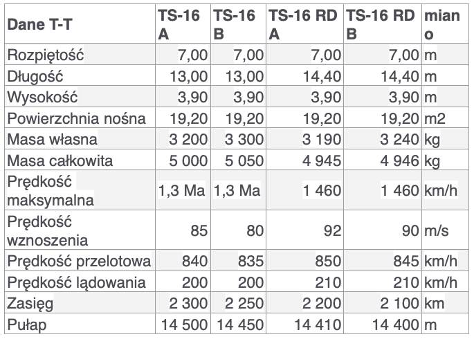
Written by Karol Placha Hetman