Kraków 2014-09-24
Zarys historii nawigacji.
Automatyczne systemy lądowania.
Systemy lądowania NDB, USL, RSP, ILS zostały omówione w innych rozdziałach. W tej części przedstawimy historyczne wydarzenia, które wywarły wpływ na technikę lądowania.
Prolog.
W 40-latach XX wieku, w USA badania przeprowadzone przez Urząd Poczty wykazały, że 76 % przymusowych lądowań było wymuszonych złą pogodą. Dlatego w USA i UK podjęto szeroko zakrojone działania nad stworzeniem systemu ślepego lądowania, który umożliwiłby lądowanie w nocy i przy złej pogodzie. W działaniach zaangażowały się rządy obu wymienionych krajów. Nie miało znaczenia, czy samolot będzie wojskowy, czy cywilny. Główne prace badawcze trwały od 1949 roku do 1965 roku. Pierwszym rezultatem prac było opracowanie systemów oświetlenia rozciągniętych od progu drogi startowej na długości 1 mili w obu kierunkach. System okazał się dobry, ale pozostawiał niedosyt. Tym bardziej, że nie na wszystkich lotniskach było miejsce na rozwiniecie takich świateł. Po raz kolejny zwrócono uwagę na systemy radiowe. Badacze doszli do wniosku, że system musi opierać się na urządzeniach naziemnych i zamontowanych na pokładzie samolotu. Wszystkie samolot musiałby być wyposażony w czujnik do odbioru sygnału, super-precyzyjny wysokościomierz i niezawodny autopilot. Stosowane wówczas wysokościomierze barometryczne były niedokładne. Dlatego opracowano radio-wysokościomierze. Takie urządzenie pozwala na precyzyjne określenie pułapu lotu nad ziemią. Dokładność wyniosła 1-2 m. Sygnał radiowy ścieżki był emitowany z urządzenia zamontowanego na końcu drogi startowej. Pierwszego automatycznego lądowania w UK dokonał porucznik Noel Adams na testowym samolocie Vickers Varsity, w dniu 3.07.1950 roku. Aby system został powszechnie wprowadzony należało udowodnić, że jest bezpieczny. Norma wymagała; 1 wypadek na 10 000 000 lądowań. Rozgorzała wieloletnia dyskusja. Na dodatek lotnisko, na którym prowadzono testy zostało całkowicie zamknięte, z powodu panujących tam systematycznie mgieł. Testy przeniesiono na lotnisko Heathrow.
Samolot Vickers Varsity to brytyjska maszyna przeznaczona dla treningu załóg Royal Air Force. Prototyp pierwszy lot wykonał w dniu 17.07.1949 roku, a w 1951 roku, samolot został wprowadzony do służby w RAF, gdzie służył przez 25 lat. Vickers Varsity to metalowy dolnopłat wyposażony w dwa silniki tłokowe. Na samolocie szkoliły się głównie załogi bombowców w nawigacji i bombardowaniu (celowaniu w zrzucie bomb). Na samolotach tych szkoliły się załogi bombowców serii V; Valiant, Vulcan, Victor.
Podstawowe dane samolotu Vickers Varsity; wymiary rozpiętość 27,20 m, długość 19,10 m, wysokość 7,32 m, masa własna 11 350 kg, całkowita, 16 550 kg, paliwa 2 800 kg, prędkość max 470 km/h, prędkość przelotowa 420 km/h, pułap 6 700 m, zasięg 2 000 km. Zespół napędowy; dwa silniki tłokowe Herkules 230 o mocy 2 x 1 975 KM. Wersja transportowo-desantowa zabiera na pokład 36 spadochroniarzy.
System wspomagania lądowania ewoluował. Ostatecznie w 1964 roku, system został przyjęty do lotnictwa komercyjnego. W dniu 4.11.1964 roku, odbyło się pierwsze komercyjne lądowanie z użyciem systemu ILS w UK (lotnisko Heathrow) przy widoczności zaledwie 40 m.
USA 20-lata XX wieku.
W drugiej połowie 20-lat XX wieku, urządzenia radiowe były już na tyle rozwinięte, że można było myśleć o wykorzystaniu patentu Otto Schellera z 1907 roku, na zasadę prowadzenia wzdłuż linii równych sygnałów radiowych. W 1921 roku, amerykańscy inżynierowie F.H. Engel i F.W. Dunmore opracowali konstrukcję trasowej radiolatarni kierunkowej niskiej częstotliwości LFB (Low Frequency Beacon, albo LF-RNG – Low Frequency Radio Range). Cztery anteny nadawały kierunkowo znaki alfabetu Morse’a A (.-) i N (-.), formując dwie lub cztery wąskie strefy nakładania się znaków z równą głośnością. Pilot sterował tak, by w słuchawkach zwykłego odbiornika średniofalowego słyszeć sygnał ciągły.
Późniejsze prace Dunmore’a nad systemem DLB (Dunmore Landing Beam) i BSS (Bureau of Standards System) prowadziły w kierunku systemu podejścia do lądowania przy ograniczonej widzialności: system miał wyznaczać kurs lądowania, kąt schodzenia i odległość do punktu przyziemienia. Systemy te wyznaczały kierunek lądowania metodą równych sygnałów, pochodzących z nadajnika z dwoma antenami. Zamiast znaków alfabetu Morse’a użyto modulacji tonami 65 i 86.7 Hz. Na pokładzie samolotu pilot dysponował prostym częstotliwościomierzem wibracyjnym, pełniącym funkcję wskaźnika. Kotwiczki dwóch elektromagnesów, podłączonych do wyjść odbiorników miały różną długość; jedna wpadała w rezonans przy 65 Hz, druga przy 86.7 Hz. Wzdłuż optymalnego kierunku podejścia amplituda drgań kotwiczek była równa.
Bardziej zaawansowany system BSS miał zespół urządzeń wyznaczających ścieżkę schodzenia. Odbicie fal od powierzchni gruntu powodowało jednak, że uzyskiwana w praktyce linia równych sygnałów była krzywą, trudną do interpretacji. Dla poprawy dokładności stosowano dodatkową naziemną radiolatarnię bezkierunkową w roli znacznika. Nadawała ona sygnał 40 Hz. Dodatkowo, odczyt na pokładzie samolotu był dokonywany precyzyjnym amperomierzem, który za każdym razem należało kalibrować.
System BSS (Bureau of Standards System) należy uznać za prekursora systemu ILS. Testy systemu wypadły pozytywnie, lecz ich praktyczne zastosowanie było niezwykle trudne. Dlatego system BSS oraz DBL nie wyszły ze strefy badań. Koszt i efekt nie były porównywalne.
W efekcie stosowano prosty system oparty na radionamierniku zamontowanym na polu wzlotów. Samolot po przejściu nad radionamiernikiem utrzymywał kurs przeciwny do kierunku lądowania przez określony czas. Następnie wykonywał zwrot o 180 stopni i podchodził do lądowania korygując kierunek według wskazań operatora radionamiernika. Ścieżkę schodzenia pilot określał według zegara, wysokościomierza i wiatru.
Innym systemem tego typu było podejście według dwóch radiolatarni średniofalowych LFB albo NDB (200 do 600 kHz). Kierunek podejścia był wskazywany przez radionamiernik pokładowy, nazywany radiopółkompasem. W 1930 roku, kapitan Hagenberger z lotnictwa wojskowego USA skonstruował automatyczny radiokompas, który samoczynnie i w sposób ciągły wskazuje kierunek na radiolatarnię. Do podejścia według dwóch radiolatarni przydawały się dwa zestawy radiokompasu na pokładzie. Metoda taka jest stosowana do dziś jako podejście na dwie NDB.
Germański system Lorenz i Knickebein.
Powszechnie uważa się, że pierwszy radiowy udany system podejścia do lądowania został opracowany przez germańskiego naukowca Ernsta Kramara, w 1932 roku. System nawet nazwano Lorenz. W tym czasie powstało kilka podobnych eksperymentalnych systemów. Nowością w systemie Lorenz było zastosowanie fali krótkiej (30-40 MHz). Krótka fala zwiększyła dokładność naprowadzania. Dodatkowo, pasmo fal metrowych było w 30-latach mało używane, więc nie było problemów z zakłóceniem fal używanych do korespondencji radiowej załogi samolotu z personelem naziemnym. Poza tym system nie był rewolucyjny. Wykorzystywał zasadę równych sygnałów oraz modulację wykorzystywaną w telegrafii. Przy odchyleniu w prawo sygnały były długie, czyli kreski, a przy odchyleniu w lewo sygnały były krótkie, czyli kropki. W osi sygnał powinien być ciągły, bo kropki wchodziły między kreski. Zasięg systemu Lorenz wynosił około 48 km i był w pełni satysfakcjonujący. System Lorenz na podejściu, w osi pasa miał dwa markery, które pracowały na częstotliwości 38 MHz. Dalszy nadawał kreski tonem niskim, bliższy nadawał kropki tonem wysokim. Fale były emitowane przy pomocy lamp elektronowych.
Test systemu odbył się jesienią 1933 roku, a miejscem było lotnisko Tempelhof. Do testów użyto samolotu Junkers 52/3m. Testy wypadły pomyślnie, a ponieważ system zaoferowano na sprzedaż, dlatego już w 1936 roku, był on zainstalowany na około 40 lotniskach w Europie. System Lorenz został zakupiony także przez Rzeczpospolitą Polskę i zainstalowano w 1937 roku, na lotnisku Okęcie (kierunek podejścia 310 stopni, a radiolatarnia stała od strony Alei Krakowskiej) oraz we Wilnie na lotnisku Porubanek. W 1938 roku, system pojawił się na lotnisku w Gdańsku-Wrzeszczu.
W germanii system Lorenz ewoluował w kierunku zastosowań typowo militarnych. Pojawił się system Knickebein, który posłużył do naprowadzania samolotów bombowych. Germańcy wykorzystali go w pierwszym okresie drugiej wojny światowej w atakach bombowych na GB. W skrócie, system Knickebein, był rozwinięciem systemu Lorenz z mocniejszymi nadajnikami i dużo większymi antenami. Podstawą systemu Knickebein były dwa nadajniki emitujące sygnały alfabetu Morse’a (kropki i kreski) na falach UKF na częstotliwości ok. 30 MHz (zwykle 30 lub 31,5 MHz). Zasięg do 300 km. Natomiast na samolotach bombowych umieszczono odbiorniki o znacznie większej czułości niż w systemie Lorenz. Samolot podążał zgodnie z sygnałem nadajnika, które ustawiony był na cel. Jeżeli samolot podążał właściwym kursem pilot słyszał w słuchawkach sygnał ciągły. Szerokość tego sygnału wynosiła około 365 m. Zejście z kursu objawiało się zwiększonym natężeniem kresek lub kropek. Nad celem wiązka sygnału, według którego leciał bombowiec, krzyżowała się z sygnałem drugiego, innego nadajnika. Sygnał ten odbierał inny odbiornik, a był on słyszany przez bombardiera. Był to dla niego sygnał do rzutu bomb. Nadajniki umieszczano na wzniesieniach i masztach, aby ich wysokość nad terenem wynosiła minimum 30 m, bo to zapewniało wystarczający zasięg. Pierwsze nadajniki ustawiono na terenie germanii. Po zajęciu Francji zamontowano je bliżej Wysp Brytyjskich. Jednak UK zaczęła stosować urządzenia zakłócające i skuteczność systemu drastycznie spadła.
Brytyjski system SBA.
W UK, według schematu systemu Lorenz opracowano system SBA (Standard Beam Approach). Produkcję seryjną podjęła firma Standard Telephones And Cables (STC). System pracował na sześciu kanałach zakresu 35-40 MHz. Szybko pojawiła się odmiana z płynną regulacją.
Z początkiem 1940 roku, w UK opracowano jeszcze inny system wspomagający lądowanie w złych warunkach atmosferycznych. System nazwano Blind Approach Beacon System (ślepe nawigacyjne podejście) lub Beam Approach Beacon System (wiązka nawigacyjnego podejścia) w skrócie BABS. System był rozwijany i modyfikowany, ale w sferze badawczej.
Amerykański system ITT.
W USA według schematu systemu Lorenz system lądowania opracowała i budowała firma International Telephones and Telegraph (ITT). Radiolatarnia kierunku pracowała z częstotliwością 110 MHz, a radiolatarnia ścieżki 94 MHz. Poprzez staranne dopracowanie systemów antenowych i filtrów odbiornika, uzyskano wiązkę ścieżki schodzenia prostą do wysokości 200 m. Dla samolotów opracowano specjalny krzyżowy wskaźnik, popularny do dnia dzisiejszego. Dzięki niemu pilot nie musiał się non stop wsłuchiwać w sygnały emitowane przez słuchawki, co nie było najwygodniejsze. Wskaźnik ten został przejęty do zestawów pokładowych ILS. W systemie ITT dodano trzeci, środkowy marker na podejściu.
Blokada Berlina.
Zanim jednak przedstawimy więcej informacji o automatycznych systemach lądowania 50-lat XX wieku, musimy wspomnieć o niezwykłym wydarzeniu w historii Europy, jakim była blokada Berlina przez państwo moskiewskie w okresie 1948 – 1949.Blokada Berlina, a dokładnie Berlina Zachodniego była jednym z pierwszych poważnych kryzysów pierwszej zimnej wojny na linii Wschód-Zachód (1946 – 1975). Wraz z upływem czasu od zakończenia drugiej wojny światowej stosunki między CCCP, a Zachodem pogarszały się, co znajdowało odzwierciedlenie w pertraktacjach na temat przyszłości Germanii. CCCP celowo utrzymywały wschodnią germanię w kryzysie gospodarczym i walutowym, poprzez stały dodruk reichsmarek. Na rynku były takie ilości pieniędzy, że w wymianie barterowej zaczęto używać papierosów. W dniu 20.06.1948 roku, Zachód, bez konsultacji z CCCP wprowadził markę niemiecką, dokonując reformy walutowej. Kreml obawiał się, że straci kontrolę nad swoją częścią germanii i w nocy 23/24.06.1948 roku, zarządził blokadę zachodnich sektorów Berlina odcinając dostawy energii elektrycznej i zamykając drogi. W pułapce znalazł się sektor USA, UK i Francji. Mocarstwa Zachodnie (USA i UK) rozpoczęły tworzenie mostu powietrznego. Amerykanie swoje działania określili mianem operacji Vittles, Brytyjczycy – operacją Plainfare. Blokada trwała 11 miesięcy i zakończyła się zwycięstwem mocarstw Zachodnich, głównie USA. Lotnictwo USA i UK było w stanie dostarczać zaopatrzenie (węgiel, żywność, lekarstwa, paliwo i inne) mieszkańcom Zachodniej części Berlina w wystarczającej ilości. Władze na Kremlu, wobec fiaska prowadzonej polityki, na początku maja 1949 roku, podjęły decyzję o zdjęciu blokady. Dalszą konsekwencją było powstanie RFN (23.05.1949 rok) i NRD (7.10.1949 rok).
Łącznie w czasie trwania blokady (322 dni) w ramach mostu powietrznego odbyło się 278 228 (277 264) lotów, w których przewieziono 2 326 406 (2 323 738) ton zaopatrzenia (w tym 1,5 miliona ton węgla). Dziennie przewożono od 500 do 12 000 ton towarów. Całością operacji kierował dowódca lotnictwa USA w Europie gen. C. LeMay. Wartość przewiezionych towarów to 224 mln $. W wypadkach lotniczych zginęło 31 lotników amerykańskich i 39 lotników brytyjskich.
Operacja Vittles to most powietrzny zorganizowany przez USAF w czasie od 26.06.1948 roku, do 30.09.1949 roku. W ramach tej operacji udział wzięło około 75 000 osób cywilnych i wojskowych. Do operacji zmobilizowano wszystkie dostępne samoloty transportowe C-47. Wszyscy lotnicy biorący udział w tej operacji byli ochotnikami. Pierwsze loty wykonywały samoloty bez ładunku, aby sprawdzić jaka będzie reakcja moskali. Ta część operacji trwała 10 dni i była nieoficjalnie nazwana Clay Pigeons (gliniane gołębie, tak nazywano cele w strzelectwie). Według szacunkowych informacji w momencie wprowadzenia blokady Berlin Zachodni potrzebował prawie 1 900 ton samej żywności dziennie, aby uchronić mieszkańców przed głodem, dodatkowo potrzebny był węgiel dla elektrowni oraz paliwa płynne. W momencie wprowadzenia blokady USAF w Europie posiadało tylko 100 samolotów Douglas C-47, które mogły korzystać z trzech lotnisk – Gatow (w brytyjskim sektorze Berlina), Tempelhof (w sektorze Amerykańskim) i Tegel w sektorze francuskim). Francuzi nie brali aktywnego udziału w mostach powietrznych, ale udostępnili swoje lotnisko do użytku USAF. Szybko okazało się, iż potrzebne są większe samoloty. W dniu 28.06.1948 roku, do Germanii przyleciały pierwsze Douglas C-54 Skymaster. W ciągu 14 dni było ich już około 500 maszyn. Samoloty Douglas C-54 Skymaster były podstawowymi maszynami, które wykonywały loty 24 godzinę na dobę, lądując w Berlinie co 3 minuty.
Największym problemem okazały się mgły. W dniu 13.08.1948 roku, z powodu mgły rozbiło się kilka samolotów w powietrzu i na lotnisku. W powietrzu utworzył się korek. Dlatego dowództwo operacji wprowadziło trzy zasady. Po pierwsze; Nawet w idealnych warunkach pogodowych załogi miały latać według przyrządów. Po drugie; Było tylko jedno podejście do lądowania. W przypadku niepowodzenia samolot miał powrócić z pełnym ładunkiem do bazy. Po trzecie; załogi nie mogły opuszczać maszyny w Berlinie. Przy doskonale zorganizowanym rozładunku, cały pobyt w Berlinie trwał najwyżej 25 minut, a samoloty lądowały co 2-3 minuty.
Lotnisko Tegel, zanim mogło przyjmować duże 4-silnikowe samoloty Douglas C-54 Skymaster, zostało przebudowane. Ponieważ USAF nie posiadało samolotów zdolnych do przewozu dużych maszyn budowlanych, dlatego maszyny budowlane rozmontowywano i w częściach przewieziono do Berlina. Niektóre elementy cięto i spawano na miejscu. Pierwsze samoloty wylądowały w listopadzie 1948 roku.
Na tym nie koniec. Na początku drogi startowej były dwa 60-metrowe maszty radiowe. Były one własnościową moskali, którzy odmówili ich demontażu lub przesunięcia. Dlatego, w dniu 16.12.1948 roku, zostały one przez aliantów wysadzone w powietrze.
Do Berlina Zachodniego prowadziły trzy korytarze powietrzne, każdy o szerokości 20 mil (32 km). Północny używany był w obu kierunkach przez samoloty brytyjskie. W dwóch pozostałych latały samoloty amerykańskie – w południowym na wschód, do Berlina, w środkowym na zachód, z Berlina.
Lotnicy spotykali się z różnymi próbami paraliżowania ich zadana przez moskali. Myśliwskie samoloty CCCP przelatywały w pobliżu samolotów transportowych w małej odległości, często także strzelając tuż obok nich. Obok samolotów transportowych strzelała także sowiecka artyleria przeciwlotnicza. Samoloty transportowe były często oświetlane silnymi reflektorami. Łącznie zanotowano 733 przypadki tego typu działań.
W miarę wzrostu doświadczenia lotników, obsługi naziemnej i doskonalenia się wszystkich procedur, coraz bardziej wzrastała wydajność mostu powietrznego. W kwietniu 1949 roku, w każdym dniu przewożono przeciętnie 6 729 ton zaopatrzenia dziennie, co nie tylko zaspakajało wszystkie bieżące potrzeby, ale pozwalało na robienie zapasów.
Dla wspomagania manewru lądowania na berlińskie lotniska sprowadzono stacje radiolokacyjne. Było to pierwsze w historii lotnictwa tak szerokie zastosowanie radiolokacji w manewrze lądowania. Sama stacja radiolokacyjna to za mało. Konieczna była ścisła współpraca operatorów stacji radiolokacyjnych i załóg samolotów. Operatorzy stacji radiolokacyjnej monitorowali dokładny kurs i wysokość zbliżającego się samolotu. Przez radio ustnie przekazywali instrukcje załodze samolotu. Instrukcje obejmowały tempo zniżania i kierunek (kurs). Nie podawali natomiast odległości do początku progu drogi startowej. Ten parametr załoga określała sama, na podstawie punktów orientacyjnych (reperów) w dzień lub rozstawionych reflektorów w nocy.
Ponieważ częstotliwość podejścia do lądowania samolotów, na jednym lotnisku wynosiła nawet poniżej 6 minut, dlatego już przed trzecim zakrętem samoloty ustawiano w odpowiedniej separacji. Samoloty były tego samego typu, więc łatwo było dobrać standardową prędkość podejścia do lądowania.
Pierwsze automatyczne systemy lądowania.
Doświadczenia uzyskane przez amerykanów i brytyjczyków, podczas blokady Berlina Zachodniego pozwoliły na wskazanie istotnych elementów podejścia do lądowania, aby było ono jeszcze bardziej bezpieczne.
Jednym z pierwszych dobrych systemów precyzyjnego lądowania był brytyjski system Rebecca lub inaczej BABS (Blind Approach Beacon System), opracowany jeszcze w czasie drugiej wojny światowej. Blind Approach Beacon System w wolnym tłumaczeniu oznacza system oświetlenia ślepego lądowania. Pierwsza jego wersja powstała na początku 1940 roku. Jednak pracę wstrzymano z uwagi na inne pilniejsze potrzeby. Do tematu powrócono w 1945 roku. System jest połączeniem oświetlenia drogi lądowania i zastosowania fali elektromagnetycznej dla prowadzenia samolotu. Emiter fali umieszczono na końcu drogi startowej. Na samolocie zamontowano drugą część systemu nazwaną Rebecca. System zapewniał stałą i dokładną informację o odległości do punktu przyziemienia. Określaną metodą odzewową odległość była wyświetlana na sporym ekranie oscyloskopowym, gdzie przy pomocy siatki można było określić wymaganą wysokość dla różnych kątów ścieżki schodzenia. Wynikało to z emitowania na jedną stronę drogi startowej kropek, a na druga stronę kresek. Siła odbioru w samolocie zależy od położenia samolotu względem linii środkowej pasa. Wyposażenie samolotu określało pozycję samolotu w stosunku do tych kropek i kresek. Około 1955 roku, pojawiła się wersja oznaczona Standard Mk.9, która zamontowano na kilku lotniskach. Jednak lądowanie z BABS wymagało dużej praktyki. BABS był używany na większą skalę tylko w Zjednoczonym Królestwie, głównie przez RAF.
Automatyczne lądowania samolotów. Convair F-102 A.
Nadal pracowano nad wdrożeniem w pełni automatycznych systemów podejścia do lądowania. Należy tu mieć na myśli takie lądowanie samolotu w którym rola pilota ogranicza się wyłącznie do kontroli manewru lądowania. Automat na pokładzie samolotu, we współpracy z urządzeniami naziemnymi, sam sprowadza samolot na drogę startową i wykonuje hamowanie na dobiegu. Tylko w sytuacji awaryjnej pilot przejąłby stery maszyny. Już w połowie 50-lat XX wieku, technicznie było to możliwe. Pojawił się jednak problem niezwykle trudny do rozwiązania. Tym problemem była pogoda, która jako nieprzewidywalna może niezwykle szybko zmienić warunki aerodynamiczne samolotu podchodzącego do lądowania.
Pierwsze próby w pełni automatycznego lądowania przeprowadzono w USA samolotem Convair F-102 z początkiem 60-lat. System był jednak kosztowny i nie uwzględniał zmiennych warunków pogodowych.
Warto w tym miejscu napisać parę zdań o tym niezwykłym myśliwcu, a właściwie rodzinie; F-92, F-102, F-106. Samolot F-102 to pierwszy naddźwiękowy samolot myśliwski obrony powietrznej USA, wyposażony w stację radiolokacyjną i uzbrojony wyłącznie w 6 egzemplarzy kierowanych pocisków rakietowych Falcon klasy p-p. Koncern Convair był w tym czasie jedną z najlepszych firm lotniczych, zarówno w lotnictwie wojskowym jak i cywilnym. Założycielem firmy był R. H. Fieel. W 1923 roku, nastąpiło połączenie fabryk Dayton Wright Company i Gallaudet Aircraft Corporation. W 1943 roku, zakłady Consolidated połączyły się z zakładami Vultee Aircraft Corporstion tworząc wielką firmę pod nazwą Consolidated Vultee Aircraft Incorporated. W 1954 roku, firma połączyła się z koncernem General Dynamics Corporation, a połączone zakłady otrzymały nazwę Convair Division of General Dynamics Corporation, przy czym często używano skróconej nazwy Convair. Najważniejszymi konstrukcjami koncernu były takie maszyny jak; B-24 Liberator (1939 rok), B-36 (1947 rok), B-58 Hustler (1956 rok), F-102 (1954 rok), XF2Y-2 Sea Dart (1954 rok). Samolot F-106 powstał już pod nową marką General Dynamics.
Trzeba wspomnieć, iż samolot Convair F-102 był ściele powiązany z systemem kierowania opracowanym przez firmę Hughens MG-3/10, który był pierwszym na świecie tego typu rozwiązaniem.
Na podstawie doświadczeń uzyskanych podczas budowy i badań nad samolotem doświadczalnym XF-92, podjęto w 1951 roku, prace nad samolotem bojowym. Oznaczono go YF-102 i nadano nazwę Delta Dagger, która nawiązuje do kształtu maszyny. Projektowanie i budowa pierwszego prototypu trwała 18 miesięcy. Pierwszy lot wykonano 24.10.1953 roku. YF-102 oprócz nowatorskiego układu aerodynamicznego odznaczał się niespotykanie dużą masą startową wynoszącą ponad 12 000 kg. Z projektem firma wiązała ogromne nadzieje. Jeszcze podczas projektowania USAF złożyło zamówienie nie tyko na dwa prototypy, ale także podjęto decyzje o przygotowaniu produkcji seryjnej. Niestety w jednym z pierwszych lotów, podczas startu silnik odmówił pracy i maszyna uległa rozbiciu. Ta strata wywołała opóźnienie programu. Dopiero z końcem grudnia 1953 roku, ukończono budowę drugiego prototypu. Jego oblot nastąpił 11.01.1954 roku. Samolot ten nieznacznie różnił się od poprzednika. Wprowadzono w nim drobne zmiany podyktowane uzyskanymi wcześniej danymi charakterystyk stateczności i sterowności. Maszyna YF-102 jednak nie osiągnęła przewidywanej prędkości naddźwiękowej. Firmie groziło zerwanie kontraktu i związane z tym konsekwencje finansowe. Ponieważ wymiana silnika nie wchodziła w rachubę, gdyż nie było odpowiedniej turbiny, jedynym sposobem było zmniejszenie oporu samolotu. Cel ten osiągnięto poprzez przekonstruowanie płatowca zgodnie z wcześniej odkrytą „regułą pól”. W rejonie skrzydeł kadłub otrzymał charakterystyczne przewężenie, cały kadłub wydłużono, szczególnie jego przednią część. Po bokach tylnej części kadłuba dodano owiewki. Opór czołowy zmalał aż o 25 %. W ten sposób powstał nowy samolot, któremu nadano oznaczenie YF-102 A. Pierwszy lot wykonano na nim 20.12.1954 roku i już następnego dnia przekroczono na nim prędkość dźwięku w locie poziomym na wysokości 10 000 m. Teraz już prace potoczyły się bez przeszkód. Już w połowie 1955 roku, pierwsze maszyny F-102 A trafiły do jednostek wojskowych. Samoloty F-102 A wyposażano w silniki Pratt-Whitney J57-P-35 o ciągu z dopalaniem 76,54 kN (7 750 kG).
Kontrakt przewidywał także budowę wersji szkolnej, gdyż na takim samolocie jeszcze w wojsku nikt nie latał i przewidywano trudności. Pierwszy lot wersji dwumiejscowej wykonano 8.11.1955 roku. Samolot otrzymał kabinę z miejscami obok siebie. Spowodowało to konieczność przebudowania chwytów powietrza. W przyszłości było to przyczyną trudności eksploatacyjnych. Na dodatek osiągi samolotu drastycznie spadły. Maszyny dwumiejscowe otrzymały uzbrojenie identyczne jak wersje jednomiejscowe, co w lotnictwie USAF było wówczas wyjątkiem od reguły. Dzięki temu samolot wykonywał zadania treningowe i bojowe.
Zgodnie z założeniami projektu, myśliwiec służy głównie do przechwytywania i zwalczania około dźwiękowych strategicznych samolotów bombowych i rozpoznawczych. O randze samolotu świadczy fakt, iż planowano zbudowanie 1 750 sztuk, czego jednak nie zrealizowano. W drugiej połowie 50-lat myśliwiec ten stanowił podstawę obrony powietrznej USA. Działał on w ścisłej współpracy z naziemnym systemem naprowadzania, który oznaczono WS 201 A. Podstawowym wyposażeniem maszyny jest układ kierowania ogniem MG-10 Hughens, którego głównym elementem jest stacja radiolokacyjna. Wykrywa ona cele z odległości 50 km., pojedynczy cel rozpoczyna śledzić automatycznie z odległości 25 km. Początkowo była to wersja MG-3 Hughens. Jako uzbrojenie przejściowo zastosowano niekierowane pociski rakietowe. Docelowym i jedynym uzbrojeniem stały się kierowane pociski rakietowe Falcon. Całe uzbrojenie umieszczono w kadłubowej komorze, którą otwierano przed oddaniem strzału.
Samoloty F-102 A stacjonowały nie tylko na terenie USA, ale i w RFN, UK, na Islandii, na wyspach Pacyfiku. Na Islandii maszyny stacjonowały do 1973 roku. Z chwilą wprowadzania na uzbrojenie sowieckich samolotów z większą prędkością lotu i większym pułapem przydatność F-102 A zmalała. W 1960 roku, maszyny zaczęto przekazywać do Gwardii Narodowej.Ogółem zbudowano 947 (990) sztuk, w tym 10 egzemplarzy YF-102, które w większości przebudowano na F-102 A, 4 egzemplarze YF-102 A, 870 egzemplarze F-102 A i 63 (110) egzemplarze TF-102 A. Produkcję ukończono w 1958 roku.
Niewielką grupę samolotów F-102 A użyto do działań wojennych w Wietnamie, jednak efekty ich użycia były słabe. Samolot z założenia nie był przeznaczony na eksport, ale na przełomie 60-tych / 70-tych lat kilkanaście samolotów sprzedano Grecji i Turcji. W latach 70-latach 8 egzemplarzy przebudowano na samoloty-cele i eksperymentalne PQM-102 A i QE-102 A. Pierwszy z nich oblatano 13.08.1974 roku.
Samolot F-102 jest bardzo zautomatyzowany. Konstruktorzy całkowicie zrezygnowali z uzbrojenia lufowego, a kierowane pociski rakietowe umieścili w komorach w kadłubie. Zrezygnowano z powieszeń zewnętrznych, chociaż samolot pod skrzydłami może przenosić dwa dodatkowe zbiorniki paliwa, które służą wyłącznie do przebazowania samolotu. Podstawowe uzbrojenie składa się z 6 kierowanych pocisków rakietowych klasy p-p GAR-1 Falcon, umieszczonych wewnątrz kadłuba. Ciekawie rozwiązano komory dla 6 pocisków. Płatowiec posiada 3 komory umieszczone obok siebie. Jedną centralną i dwie boczne. W każdej z nich umieszcza się dwa pociski w układzie jeden za drugim. Boczne komory mają zawiasy w dole. Wyrzutnie mają kinematyki wysuwające pociski z kadłuba. System jest tak skonstruowany, że można w danej chwili odpalić tylko jeden pocisk.
Wykaz pocisków Falcon;
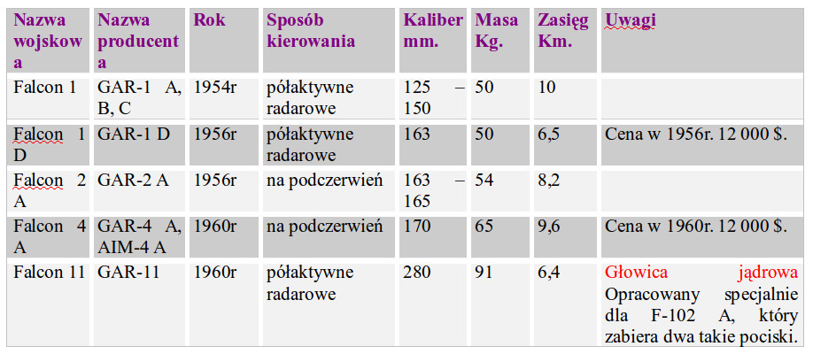
Wyposażenie samolotu do kierowania pociskami ma masę 550 kg. Zważywszy na układy elektryczne i elektroniczne stosowane w USA w 50-latach XX wieku, to i tak masa ta nie była duża. System jest skomplikowany i wymagał wysokich kwalifikacji personelu. Składała się ona z przekaźników mechanicznych, elektronicznych lamp próżniowych, serwomechanizmów i mechanicznych przekładni. Instalacja elektryczna jest zasilania przez silnik-generator, który dostarcza prąd standardowo 28 V, o częstotliwości 115 i 400 Hz. System MG-10 ma wbudowany system Built In Test (BIT), który jest obsługiwany przez personel naziemny, aby utrzymać MG-10 w stałej gotowości. Obsługa naziemna ma również możliwość dynamicznego sprawdzenia celności zestawu rakietowego, Dynamic Accuracy Test Set (DATS cart). Poprzez kable łączono samolot ze stanowiskiem testowym zwanym Radom. Osłona dielektryczna anteny stacji radiolokacyjnej przykrywana była nieprzepuszczalną osłoną (kocem). Zestaw testowy generuje sztuczny cel, który obsługa mogła zblokować ze śledzeniem celu i oglądać przebieg ataku wykonywany przez MG-10. Test może obejmować także otwarcie drzwi komory pocisków, ich wysuniecie na wyrzutniach i przygotowanie pocisku do odpalenia. Ocena systemu MG-10 jest standardowo wykonywana w powietrzu po starcie i zajęciu pułapu przelotowego. Służył do tego jeden z pocisków symulatorów załadowanych na wyrzutni. Pocisk-symulator ma zamontowaną kamerę, która rejestruje przebieg teoretycznego ataku. System MG-10 został zmodyfikowany i ulepszony do MG-13 i zamontowany na samolocie F-101 Voodoo.
Rozwinięciem F-102 A był samolot F-106 A, który otrzymał poprawioną aerodynamikę i nowszy, mocniejszy zespół napędowy J-75 (ciąg 11 800 kG). Dzięki temu osiągi maszyny uległy poprawie. Prędkość max to Ma-2,3, pułap operacyjny 17 370 m, taktyczny promień działania 925 km. Zmniejszono liczbę pocisków rakietowych z 6 do 4 sztuk. Układ kierowania uległ modyfikacji.
Start samolotu przeprowadza pilot. Półautomatyczny, naziemny system kierowania może przejąć sterowanie samolotem tuż po starcie maszyny. System wykonuje wznoszenie i kieruje samolot w rejon nieprzyjaciela. Rejon ten jest zlokalizowany przez naziemną stację radiolokacyjną. W rejonie celu pokładowa stacja radiolokacyjna rozpoczyna przeszukiwanie przestrzeni w celu znalezienia intruza. Po zlokalizowaniu intruza pokładowa stacja radiolokacyjna przestawia się na śledzenie celu. Wówczas następuje identyfikacja celu; swój-obcy. System MG-10 prowadzi automatycznie samolot podczas ataku i bez udziału pilota odpala wybrany pocisk rakietowy. Rolą pilota jest tylko odbezpieczenie pocisków. Bezpośrednio po wykonanym ataku system automatycznie wyprowadza samolot z kursu bojowego i przestawia celownik pokładowy (radiolokator) na poszukiwanie następnego celu. Poszukiwanie i zwalczanie kolejnych celów jest ograniczone ilością paliwa. Samolot jest także automatyczne prowadzony na lotnisko. Pilot przejmuje stery tuż przed przyziemieniem. W założeniach programu była także funkcja całkowicie automatycznego startu i automatycznego lądowania. To jednak nie zostało zrealizowane w pełni. Pilot może także przejąć stery w dowolnym momencie misji.
System MG-10 składa się z następujących elementów; pokładowa stacja radiolokacyjna z ekranem, data link (źródło danych), komputer, automatyczny system kontroli lotu, missile auxiliaries (zestaw pocisków rakietowych), optical sight (celownik optyczny). Radar pracuje w następujących zakresach; przeszukiwanie przestrzeni, śledzenie celu, mapowanie terenu. Radar jest w stanie wykryć kilkanaście celów jednocześnie. Sama stacja radiolokacyjna to wersja oznaczona APX-26 lub APX-27. Poprzez data link system otrzymuje informacje o pułapie celu. Do komputera dostarczane są z radaru informacje o; odległości celu, położenie kątowe celu, stopa kątowa celu. Komputer wypracowuje sekwencję instrukcji kierowania samolotu przed rozpoczęcie śledzenia celu. Z komputera dane trafiają do automatycznego systemu kontroli lotu, ekranu stacji radiolokacyjnej i zestawu pocisków rakietowych. Automatyczny system kontroli lotu ma trzy funkcje pracy; atak na cel, pilot assist (pilot automatyczny), AILAS. Pilot assist to pilot automatyczny, a jednocześnie zobrazowanie parametrów lotu na desce rozdzielczej w kabinie pilota. AILAS to pokładowy ILS receivers approach course, czyli odbiornik automatycznego kursu podejścia do lądowania. Zestaw pocisków rakietowych składa się z bloku elektronicznego połączonego z pociskami rakietowymi, które są dwu rodzajowe; sterowanie radiolokacyjne oraz sterowane na podczerwień. Wspomaganiem jest celownik optyczny.
Naziemne stanowisko radiolokacyjne (GRI) prowadzi samolot do określonego punktu, w którym będzie można rozpocząć poszukiwanie celu powietrznego. We wspomnianym punkcie uruchamiany jest radar pokładowy. Następuje korekta kursu i pułapu myśliwca. Na ekranie pokładowej stacji radiolokacyjnej pojawia się plamka, która wskazuje cel. Dokładnie jest to punk celu na kursie kolizyjnym. Samolot jest tak sterowany, aby plamka celu znalazła się w centrum ekranu. Kiedy to nastąpi (przez odpowiednio długi czas), pojawia się dodatkowy okrąg, którego wielkość wskazuje odległość do celu, a ściśle odległość do punktu w którym może nastąpić odpalanie pocisku do celu na kursie kolizyjnym. W tym czasie następuje identyfikacja celu; swój-obcy. Okrąg na ekranie się zmniejsza, do momentu osiągnięcia odpowiedniego kontaktu w odległości. Po weryfikacji i uznaniu celu za obcy, następuje uzbrojenie pocisków rakietowych i wybór odpowiedniej rakiety; sterowanej radiolokacyjne lub termicznie. Czynność tę wykonuje pilot na specjalnym panelu missile auxiliaries. W centrum panelu jest podstawowy przełącznik, a w okienku pokazuje się typ wybranego pocisku. Pilot przed sobą ma drążek sterowy przypominający wolant z dwoma rękojeściami umieszczonymi blisko siebie. Jeśli atak ma być wykonany przez pilota, to pilot przy pomocy lewej rękojeści drążka sterowego nakierowuje znacznik pocisku na plamkę celu, aby pocisk uchwycił cel. W tym momencie na ekranie są dwa okręgi o wspólnym środku umieszczone centralnie. Samolot jest prowadzony automatycznie, cały czas utrzymując plamkę celu w centrum ekranu. Pilot w tym czasie nie trzyma drążka sterowego. Na ekranie oba kręgi się zmniejszają i w pewnym momencie pojawia się znacznik X, co oznacza odpalanie pocisku w stronę celu. Samolot wychodzi automatycznie z ataku lub stery przejmuje pilot. Kiedy pocisk eksploduje, na ekranie pojawia się ponownie znacznik X. Pilot nie jest w stanie ocenić wykonanego ataku, chyba, że miał kontakt wzrokowy. Ocenę ataku wykonują samoloty rozpoznawcze lub służby naziemne.
W wyposażeniu samolotu pozostawiono celownik optyczny. Jest on jednak bardzo nowoczesny i ma cechy ówczesnego HUD. Pilot przed sobą widzi dwa białe okręgi ze wspólnym środkiem, na tle przestrzeni poza samolotem. Sterowanie prowadzone jest tak, aby uchwycić cel w środek. Pilot odpala pocisk rakietowy sterowany głowicą termiczną.
W tym okresie rozwoju zbrojeń nie było mowy o walce manewrowej. Weźmy pod uwagę, że celami miały być bombowce CCCP i ich samoloty eskortowe, które mogły zaatakować terytorium USA. Samoloty F-102 A i F-106 A są przykładem klasycznego samolotu przechwytującego, o wysokim stopniu zautomatyzowania. Samolot ten jest ogniwem kompleksu obronnego systemu OPL.
Lądowanie automatyczne F-102 A.
Pierwszą czynnością wykonywaną przez pilota jest wyłączenie panelu sterowania zestawu pocisków rakietowych. Panel sterowania radarem zawiera dwa podstawowe przełączniki. Przełącznik po lewej stronie ma pozycje; radar OFF, WARM (rozgrzewanie układów elektronicznych), ON, STBY (czuwanie radaru bez emitowania wiązki radiolokacyjnej). Przełącznik po prawej stronie ma pozycje; 6 MI (6 mil), 30 MI (30 mil), MAP (mapowanie terenu), BCN (funkcja nawigacyjna). Pilot przestawia przełącznik na pozycje BCN. Na panelu AFCS pilot uruchamia funkcję ALTITUDE HOLD (trzymać wysokość) oraz (już na prostej do lądowania) AILAS (czyli pokładowy ILS). Ożywa wówczas wskaźnik LOC. OR RANGE. Na centralnym zegarze są dwie liniowe wskazówki; pozioma i pionowa. Samolot ma być prowadzony automatycznie w taki sposób, aby obie wskazówki się krzyżowały centralnie. Podawane jest odchylenie od założonej wysokości i kursu osi drogi startowej. Dodatkowo podawany jest kurs magnetyczny.
System sprawdza się pod pewnymi warunkami. Po pierwsze dobre warunki pogodowe. Chodzi o słaby lub minimalny wiatr. System nie radzi sobie z nagłymi podmuchami wiatru i z silnym wiatrem bocznym. Po drugie. Podejście do lądowania jest długie. Ostatnia prosta ma 20 mil. Po trzecie. Na podejściu nie może być przeszkód terenowych. Nawet pojedynczych kominów lub masztów. Podstawą prowadzenia samolotu jest pokładowy radar, a echo od przeszkód terenowych wprowadza zamieszanie w pracy komputera. Po czwarte. Wymagana długość drogi startowej jest znacznie większa od klasycznego lądowania. Jest to spowodowane tym, iż systemy elektroniczne reagują wolniej, niż typowe reakcje pilota na powstałe zmiany. Po piąte. Długie podejście wymaga większego zapasu paliwa na ewentualne drugie podejście.
Firma Hughens obiecała uporanie się z większością problemów w docelowym wariancie MG-10. Jednak powstał konflikt. W docelowym wariancie planowano znacznie zwiększyć kąt podejścia do lądowania, co w efekcie podniosło prędkość pionową przyziemienia. Należałoby zwiększyć wytrzymałość podwozia i struktury skrzydeł. Na to firma Convair nie mogła sobie pozwolić. Samolot i tak miał większą masę od pierwotnie planowanej. Dokładna analiza wykazała również, że na obecnym etapie techniki, system nie jest w stanie dojść szybko zareagować na podmuchy i uskoki wiatru. Proponowane modyfikacje znacznie zwiększały i tak już ogromne koszty programu. W konkluzji stwierdzono, iż efekt nie równa się kosztom. Ostatecznie samoloty F-102 A i F-106 A nie wykonywały w pełni automatycznych lądowań.
Automatycznie lądowanie samolotów pasażerskich.
Samoloty B-747, DC-10 i L-1011 (czytamy L-ten-eleven), były pierwszymi samolotami pasażerskimi, o wielkiej pojemności, popularnie zwane szerokokadłubowymi. Szczególnie DC-10 i L-1011 powstawały na zapotrzebowanie przewozu 350-500 pasażerów na trasach średnich i krótkich, których dystans miał nawet być poniżej 500 km. Kilku przewoźników nie bardzo widziało na swoich trasach samoloty zabierające na pokład 500 pasażerów. Wskazywali liczbę 350 pasażerów. Dlatego płatowiec samolotu Lockheed L-1011 przewidziano do zabierania max 400 pasażerów, w układzie jednoklasowym. Jego zasięg max z kompletem pasażerów zaprojektowano na 4 000 NM (7 408 km). Już wówczas było wiadomo, że napędem dla nowej maszyny będą nowo opracowywane silniki Rolls-Royce RB.211 o ciągu około 170 kN. Dla tak dużego pasażerskiego samolotu wystarczyłby zespół dwóch silników. Jednak, aby maszyna mogła operować z krótszych RWY (DS), należało zwiększyć ciąg zespołu napędowego. Dlatego zdecydowano się na układ trzysilnikowy. Miało to także tę zaletę, że maszyny mogła operować nad wielkimi przestrzeniami oceanów, chociaż w tym momencie samolot projektowano typowo na rynek USA. Dwa silniki umieszczono na wysięgnikach bezpośrednio pod skrzydłami. Natomiast trzeci umieszczono w ogonie kadłuba. Chwyt powietrza umieszczono nad kadłubem, przed usterzeniem pionowym, a kanał poprowadzono łukami w kształcie litery S. W lotnictwie wojskowym, taki układ kanałów już wykorzystywano. Jednak w lotnictwie cywilnym było to pierwsze takie rozwiązanie.
W lipcu 1968 roku, przystąpiono do budowy prototypu L-1011. W dniu 17.11.1970 roku, prototyp Lockheed Tristar L-1011 Nr L-093 wykonał pierwszy lot. Załoga H. B. Dees (pilot), Ralph C. Cokely (copilot) i G.E. Fisher (development engineer). Samolot był napędzany silnikami RB.211-22 o ciągu 3 x 190 kN.
Lockheed Tristar L-1011 był produkowany do 1983 roku, a produkcja zakończyła się po zbudowaniu około 250 maszyn.Samolot był bardzo lubiany przez pasażerów. Wpływała na tę opinię; wielka przestrzeń w kabinie, szerokie fotele, doskonałe oświetlenie, znacznie cichsze od poprzedników silniki, muzyka płynąca z głośników i dobre jedzenie.
Jednak prawdziwa rewolucja zaszła w układach sterowania i ogólnego zarządzania samolotem. Nowatorski był system sterowania maszyną. Po raz pierwszy w maszynie komercyjnej seryjnie zastosowano automatyczny system lądowania. Dla pilotów było ekscytujące sterowanie tym nowoczesnym samolotem. Pilot po prostu wybierał pułap lotu i kurs, ustawiając stosownie sterowanie systemu, a samolot to wykonywał. Pilotowi pozostawało kontrolowanie trzymanych parametrów. L-1011 leciał sam i płynnie sam podchodził do lądowania. Jeden z pilotów L-1011 nazwał go „najbardziej inteligentnym samolotem, jaki kiedykolwiek latał”.
W dniu 25.05.1972 roku, weteran pilotów testowych Anthony Levier i pilot Charles Hall ze 115 pasażerami na pokładzie (pozostali członkowie załogi, pracownicy firmy Lockheed i dziennikarze), wykonali propagandowo-testowy automatyczny przelot. Start nastąpił z lotniska Palmdale w Kalifornii, a lądowanie na lotnisku Dulles w Waszyngtonie. Lot trwał 4 godziny i 13 minut. Był to pierwszy przelot, w którym od startu do dobiegu na RWY nie było rąk pilota na wolancie. Wszystko wykonała technologia dzisiaj dobrze znana pod nazwą fly-by-wire. Dzięki imponującej funkcji autopilota, TriStar L-1011 otrzymał specjalny certyfikat nadany przez FAA do lądowania podczas trudnych warunków pogodowych. Podczas gdy inne samoloty z napędem turboodrzutowym musiały być kierowane na alternatywne lotnisk, to pasażer L-1011 mógł mieć pewność, że wyląduje dokładnie tam, gdzie zaplanowane zostało lądowanie.
Linie lotnicze Eastern Airlines nazwały samolot Whisper-liner (szept-linii), ze względu na bardzo spokojny start i zauważalnie niski poziom hałasu w kabinie pasażerskiej. Samoloty L-1011 wykazały się niezwykle wysokim współczynnikiem niezawodności, który wyniósł 98,1 %.
Co spowodowało, że Lockheed L-1011 był tak niezwykły? Samolot został zaprojektowany z nadmiarem wszystkich możliwych systemów. Posiada cztery rozdzielone i niezależne systemy hydrauliczne. Wyposażono go w cztery instalacje elektryczne. Otrzymał trzy wewnętrzne (środowiskowe) systemy kontroli. Samolot otrzymał dwa niezależne podstawowe systemy kontroli lotu – Primary Flight Controls Systems (PFCS) oraz awioniczny system kontroli lotu – Avioncs Flight Control System (AFCS). System AFCS jest podwójnie zdwojony na wypadek awarii. W skład wchodzi podwójny system automatycznego lądowania, każdy z kontrolą osi (pitch, roll and yaw) pochylenie, przechylenie i odchylenie. Każdy z nich jest wyposażony w oddzielną podwójną kontrolę. Awionika L-1011 wyprzedzała konkurencję o 5-10 lat. System awioniczny L-1011 jest powiązany z automatycznym systemem lądowania ILS; prowadzi samolot na podejściu, przyziemia, prowadzi po RWY na dobiegu korygując boczne podmuchy wiatru. Systemy awioniczne są analogowe. Poprzednie doświadczenia firmy Lockheed doprowadziły do powstanie przełomowego systemu Avioncs Flight Control System. Wykorzystano doświadczenia zdobyte z programu Lockheed SR-71. Pionierskie były także systemy kontrolne, o wielu możliwościach.
Automatyczny system lądowania, powiązany z ILS podlegał pod kategorię II i III i uwzględniał warunki pogodowe. Był rozwinięty zarówno z militarnych jak i komercyjnych programów; C-141, C-5, Jet Star. Awionika L-1011 składa się z czterech głównych systemów; 1 – Autopilot/Flight Director System (główny autopilot), 2 – Stability Angmentation System (system zachowania stabilności), 3 – Speed Control System (kontrola prędkości), 4 – Primary Flight Control Electronic System (główny elektroniczny system kontrolny – komputer).
Autopilot/Flight Director System – działa podczas lotu automatycznego jak i lotu manualnego, w każdej fazie lotu. Podczas lotu automatycznego współpracuje z pozostałymi systemami, wykonując ich polecenia. Podczas pełnego lotu automatycznego pilot wykorzystuje monitor na którym przedstawiane są podstawowe informacje o locie.
Stability Angmentation System – system jest wykorzystywany zarówno w locie automatycznym jak i przy sterowaniu manualnym. System nie dopuszcza do przekraczania nakazanych parametrów aerodynamicznych.
Speed Control System – ten system także działa niezależnie czy lot jest automatyczny, czy manualny. Nie dopuszcza do przekroczenia zarówno max jak i min prędkości. Głównie czuwa nad niedopuszczeniem do przeciągnięcia podczas lądowania.Primary Flight Control Electronic System – to system, który zarządza automatycznym lotem. Także ostrzega i wskazuje poprawne działanie. Również pracuje jako interface dla manualnego systemu kontroli. Główne jego podzespoły to komputery Trim Augmentation Computer oraz Flight Control Electronic System Computer.
W modelu L-1011-500 awionika przeszła modernizację. Została określona jako Digital System. Zmiany dotyczyły komputerów i interface-ów. Testy przeprowadzono w kwietniu 1976 roku. W porównaniu do poprzednich modeli L-1011, wersja -500 stała się samolotem dalekiego zasięgu, o średniej ilości miejsc pasażerskich. Pierwszy lot L-1011-500 odbył się w październiku 1978 roku. W dalszej kolejności, firma Lockheed zamierzała wprowadzić glass cockpit. Jednak upadek programu wstrzymał te prace na etapie studiów. Co się stało? Jak nie trudno zgadnąć – katastrofa. Ale to już temat na inny artykuł.
Opracował Karol Placha Hetman