Blizna 2026-05-13
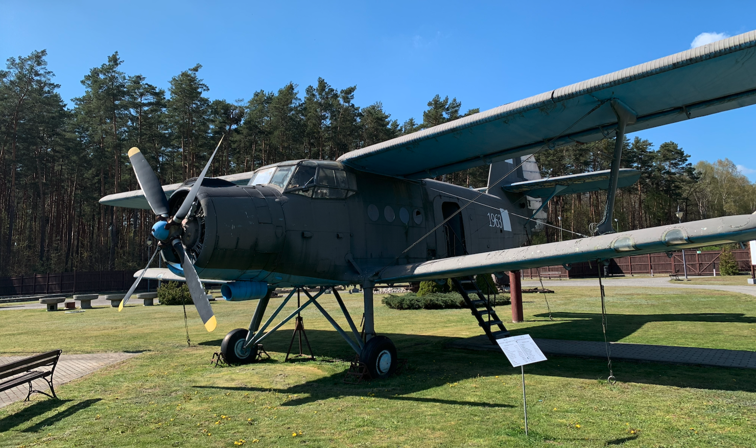
WSK PZL Mielec PZL An-2 nb 1963-1973.
The An-2 is a light transport aircraft. An exhibit at the Blizna Historical Park named after the Home Army Intelligence Service. The Blizna Historical Park is a museum and open-air historical museum located in the village of Blizna in the Podkarpacie region, primarily dedicated to the history of the German V-1 and V-2 rockets from World War II. The park is located in the Podkarpacie Voivodeship, northeast of Dębica, 25 km away. During the German occupation, an SS missile range was established here. V-1 flying bombs and V-2 rockets were tested here. The site is associated with the courageous actions of the Home Army. Home Army soldiers captured rocket fragments and handed them over to the Allies. They also organized Operation Most III, during which fragments of a V-2 rocket were flown to Great Britain. This was a huge intelligence success for the Home Army (AK). Blizna is a place of historical remembrance; With what determination and arrogance the Germans sought to eliminate other European nations. This remains unchanged.

The An-2 is a multi-role aircraft used in military and civilian aviation. It is a single-engine biplane with fixed landing gear. It is constructed of aluminum alloys in a conventional configuration. Most aircraft were built at PZL (State Aviation Works) and WSK (Communications Equipment Factory) in Mielec.
Wings.
The aircraft’s airfoil assembly consists of upper and lower wings, supports, and cables (risers). The upper wing has a span of 18.2 m and an area of 43.6 m2. The lower wing has a span of 14.2 m and an area of 28.0 m2. The wings are two-spar, metal construction with a 14% R-11 S airfoil, constant throughout. Extensive areas are covered with fabric. Fuel tanks are located in the inter-spar spaces between the upper wings. The ailerons are located on the upper wing and are mass- and aerodynamically balanced. They deflect simultaneously with the flaps, increasing their efficiency. The left aileron has an electrically controlled trim. The aileron area is 5.9 m2. Automatic slats are located on the leading edge of the upper wing along the entire span. These extend at speeds approaching stall speed. Slotted flaps are located on the upper and lower wings. The flaps have an area of 9.6 square meters. The flaps and ailerons are constructed of metal, partially covered with fabric. Brackets (stays) made of profiled duralumin sheet metal and riveted between the upper and lower wings are placed between the upper and lower wings. Cable stays are placed between the upper and lower wings to increase the stiffness of the airfoils. The left bracket houses an outside temperature sensor and a pitot tube. Two landing lights are located on the lower wings’ leading edge, and an additional taxiing light is located on the right wing.
Fuel.
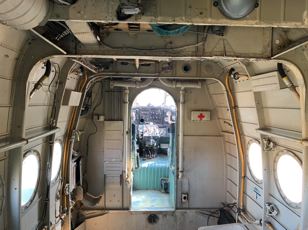
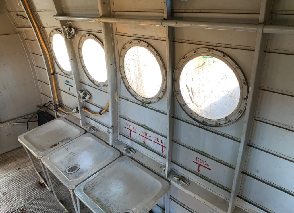
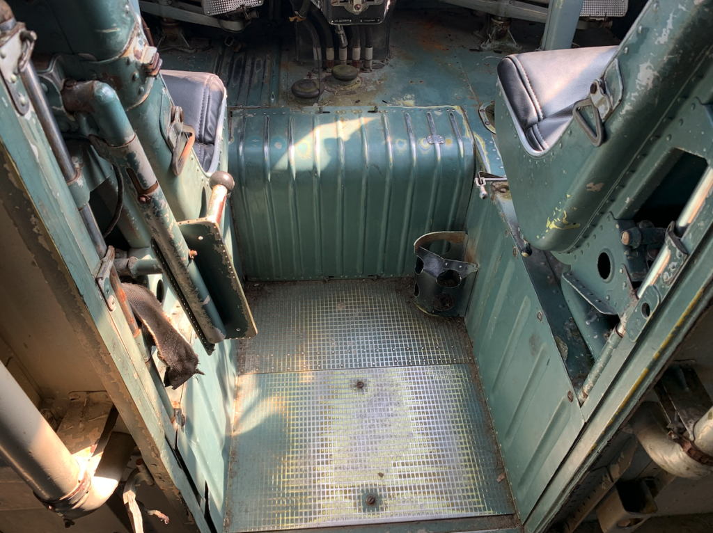
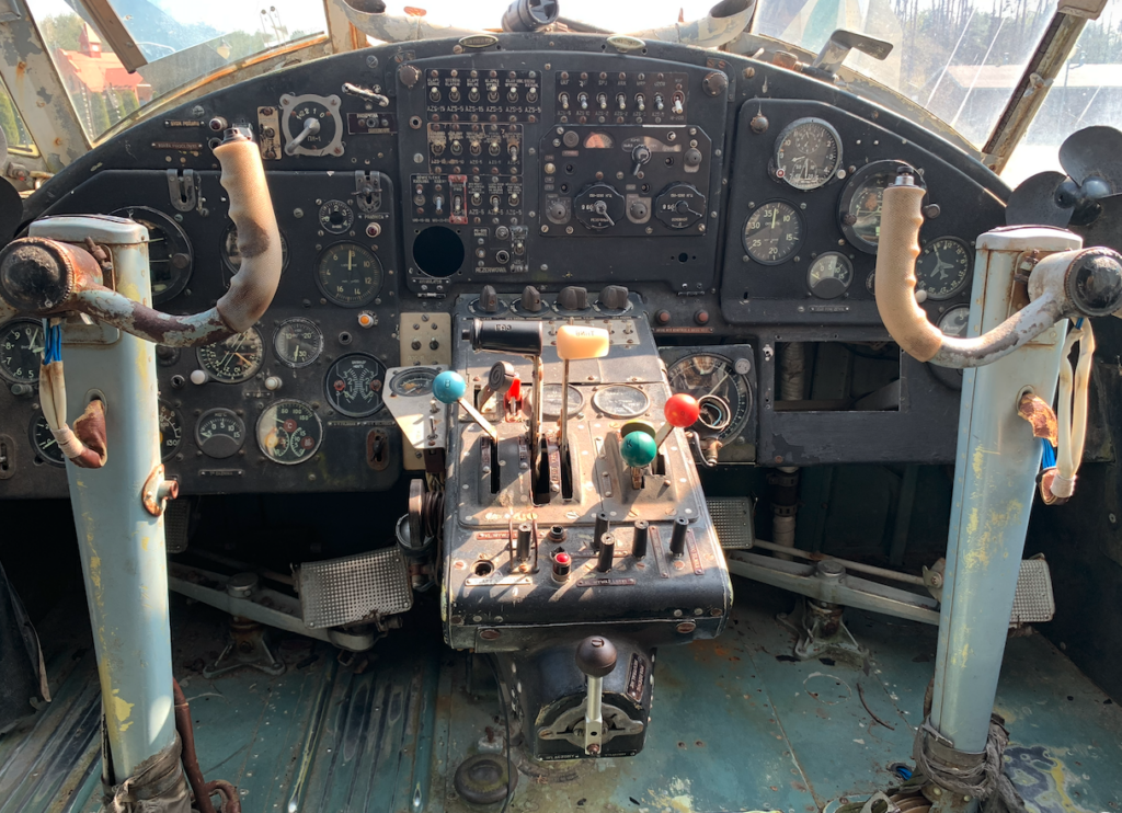
The fuselage, of semi-monocoque construction, has a roughly rectangular cross-section. It consists of ribs, stringers, a support beam, and the cargo hold floor, which acts as a power element. The fuselage is technically divided into three sections: the front with the crew cabin, the middle section, and the tail section. The fuselage begins with the powerplant, behind which the crew cabin is located. The cabin glazing is exceptionally rich in windows, with 25 windows. Due to the limited forward view, the glazing has been extended to the sides, allowing even the landing gear wheels to be seen. The glazing frame is made of a welded frame. The windows are made of organic glass. The windows in front of the pilots are heated electrically and/or by hot air. An emergency exit is located in the cabin ceiling. Two pilots occupy seats side by side in the cabin, as in a typical transport aircraft. Behind the crew cabin is the cargo hold. Cabin-cargo area dimensions: Length: 4.10 m, width: 1.60 m, height: 1.80 m. Volume: 11.8 cubic meters. The floor is reinforced. The entrance door measures 1.530 m x 1.460 m. This door houses a smaller entrance door measuring 1.420 m x 0.810 m. Four windows are located on each side of the sides. The tail section of the fuselage typically houses a toilet. The tail section also houses batteries, other equipment, and storage for on-board tools, such as wheel chocks. The crew cabin and cargo hold are heated with hot air. The cabins are ventilated, but lack air conditioning or pressurization. Therefore, versions operating at altitudes above 5,000 m use oxygen systems, to which individual pilots’ oxygen masks are attached.
Equipment.
The empennage is a classic design, divided into rudders and stabilizers. The metal structure features large surfaces covered with fabric. The horizontal tail is supported by riveted struts made of profiled duralumin sheet. The elevator is aerodynamically compensated and mass-balanced. A trim tab is located on the left half. The rudder is also mass-balanced, has aerodynamic compensation, and a trim tab. The tail profile is symmetrical and structurally similar to the wings.
Landing gear.
The landing gear is fixed, tri-pod, in the archive configuration, with a tail wheel. Oil-air shock absorbers. Drum-type pneumatic brakes are fitted to the main wheels. Brake controls are located on the left control column, and can be optionally installed on the right control column. Braking on one wheel steers the aircraft. The air tires are 800 x 260 mm. The tail wheel is mounted on a fork with a shock absorber, self-aligning in the aircraft’s direction of travel. The air tires are 470 x 210 mm. Skis can be used on slippery surfaces and ice. They have pneumatically retractable braking claws.
The aircraft’s control system is based on cables and rods. The ailerons and rudders are mechanical. The flaps and trims are electrically operated, with neutral stabilization.
The electrical system is 27 V DC, supplied by a generator. Two batteries. The electrical systems also feature voltages of 36 V and 115 V.
The air system brakes the main landing gear and sets the tailwheel in neutral. In the agricultural version, it operates the dusting or spraying system. In the water version, it operates the float controls.
The heating and ventilation system heats both cabins. Hot air comes from a heat exchanger mounted near the engine. The ventilation air intake is located on the underside of the upper wing. Additionally, two electric fans are located in the cabins.
The fire extinguishing system is installed only in the engine area and is activated by the crew. The operating medium is an inert gas. Additionally, two manual carbon dioxide fire extinguishers are located on board the aircraft.
The aircraft has standard flight instruments: airspeed indicator, altimeter, variometer, artificial horizon, tachometer, fuel gauge, magnetic compass, inductive compass, and gyroscopic heading indicator. A three-indicator engine control unit, thermometers, and pressure gauges are provided. Most of the instruments are fluorescent. An R-842 or R-805 HF radio transmitter and receiver has a radial antenna stretched between the mast and the vertical tail. It has a frequency of 2-8 MHz and a range of over 340 km. An R-860 or R-800 VHF radio transmitter has a sword antenna on the fuselage top, operating at a frequency of 118-135.9 MHz and a range of at least 100 km. An RW-UM or RW-2 radio altimeter with sound and light systems. The measurement range is 0-600 m. Dipole antennas are located under the fuselage, one 2.4 m apart. ARK-5 or ARK-9 radio compass. The antenna cable is stretched between the fuselage spine insulator and the vertical tail. It has a range of 160-180 km. It allows for course determination by ground radio stations and for landing approach in poor visibility conditions. The MRP-56P radio beacon, also known as a radio marker, is also provided. The SPU-6 onboard intercom, also known as an onboard telephone, enables communication between the three crew members on board and communication via the radio. It can also be used to listen to the radio compass. A flare gun is located on the starboard side near the pilot’s cockpit.
Engine.
ASh-62 IR, 9-cylinder, air-cooled piston engine with a planetary reduction gear and centrifugal compressor. Power: 1 x 736 kW (1 x 1,000 hp). Electric starting. The metal engine cowling, CAGI type, features automatic airflow control with shutters, thereby cooling the engine.
Fuel is stored in six tanks with a capacity of 1,200 liters. Fuel is 91 octane aviation gasoline. The oil tank holds 125 liters. The oil cooler is located on the rear frame under the engine cowling. The propeller is a 4-blade, variable-pitch propeller with hydraulic inertial blade adjustment.
In Poland, during engine modernization, fuel consumption was reduced by 20%, and the overhaul interval increased from 800 to 1,800 hours.
Various propeller types were used, all with a diameter of 2.60 (2.62) m. The leading edge always has grooves for dousing with spirit to prevent icing. The propeller type also determines the period in which it was used: W-509D7. The G.M. design. Zasławski with characteristic saber-shaped wooden blades. Used until around 1965. W-509D9. Rectangular blades with blunt-cut tips. Hub protected by a spinner. Blades made of a component: improved delta wood + aircraft-grade pine + metal mesh. Used on aircraft built by WSK Mielec. PZL AW-2, developed in the 1970s. Blades made of metal. Hub not protected by a spinner.
Data T-T An-2 TD specifications, 1960:
Wingspan 18.176 m, Length 12.735 m, Height 4.235 m, Wing area 71.51 m², Empty weight 3,445 kg, Gross weight 5,200 kg, Maximum weight 5,500 kg, Payload 2,055 kg, Payload 1,500 kg, Fuel 1,200 liters. Maximum speed 253 km/h, Minimum speed 120 km/h, Climb rate 3.5 m/s, Cruising speed 185-190 km/h, Landing speed 85 km/h, Range 900 km. Pula 4 160 – 4 400 m. Inrun 150 – 180 m. Run 170 – 180 m.
Written by Karol Placha Hetman