Kraków 2017-01-30
AL-7 turbojet engine and its development version AL-21
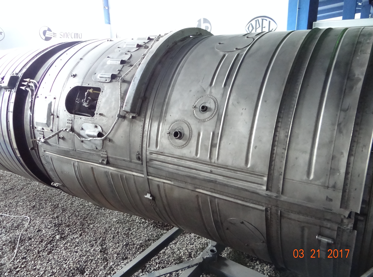
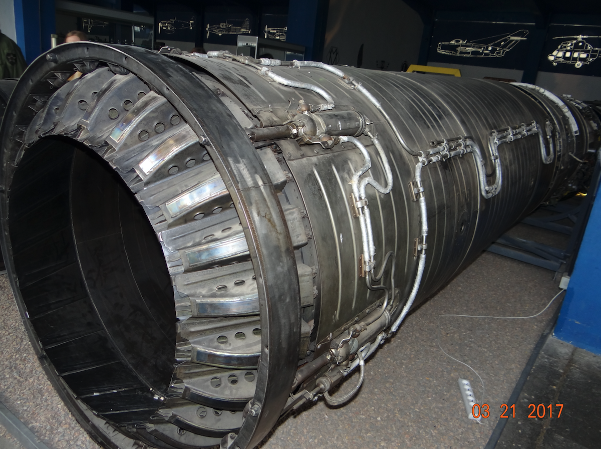
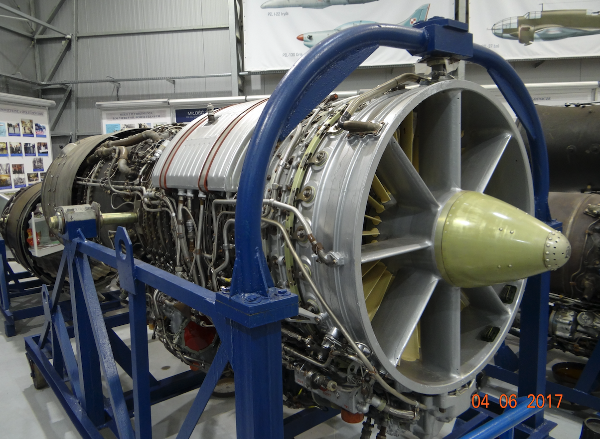
AL-7 engine. 1952 year.
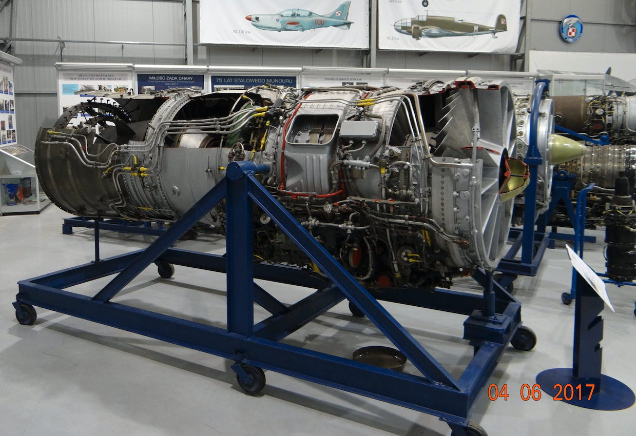
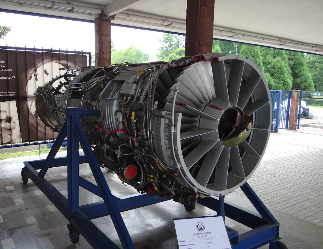
An important engine in the CCCP was the AL-7 F-1 engine, which in Archip M. Lulka’s team was called TRD-31. The engine was created at the beginning of the 50s, through the development of the AL-5 engine, especially its enlargement. The AL-7 engine was first launched in September 1952. The AL-7 engine was used to power Su-7, Su-9, Su-11, Tu-128 aircraft.
During the ground tests, the phenomenon of pumping occurred many times. Pumping is a disturbance of the air flow in the engine, causing the engine to stop working. After the modernization, the designers thought that the problem was solved. On April 24, 1959, the S-22-1, the future Su-7B, took to the air. The pumping problem returned when firing unguided missiles. This time it was caused by rocket exhaust gases. In order to prevent this, the AL-7 engine received the KS-1 installation that automatically reduces the engine speed when the missiles are used and after a while also automatically restores the initial engine speed. The installation did not fully solve the pumping problem, and therefore additional operational restrictions were introduced for flights with large S-24 unguided missiles.
The first version of the engine was called AL-7 F-100. The designation "100" meant the engine’s overhaul period, that is, overhaul after 100 hours of operation. Subsequent versions have already received the designation AL-7 F-1, and the inter-renovation life has increased to 150 hours, and then to 250 hours. For the mid-1950s, the AL-7 F-1 engine was relatively modern. Almost at the beginning of serial production, a modern solution was introduced in the engine in the form of a movable first stage of the steering wheel in the compressor and air release after the 7th stage of the compressor.
The first production series of the AL-7 F-1 (TRD-31) engine had a maximum thrust without afterburning of 66.64 kN (6,800 kG), a maximum thrust with afterburning of 94.08 kN (9,600 kG). Subsequent production versions of the AL-7 F-1 engine had a maximum thrust without afterburning of 68.65 kN (7,000 kG), and a maximum thrust with afterburning of 98.10 kN (10,000 kG).
Construction of the AL-7 F-1 engine.
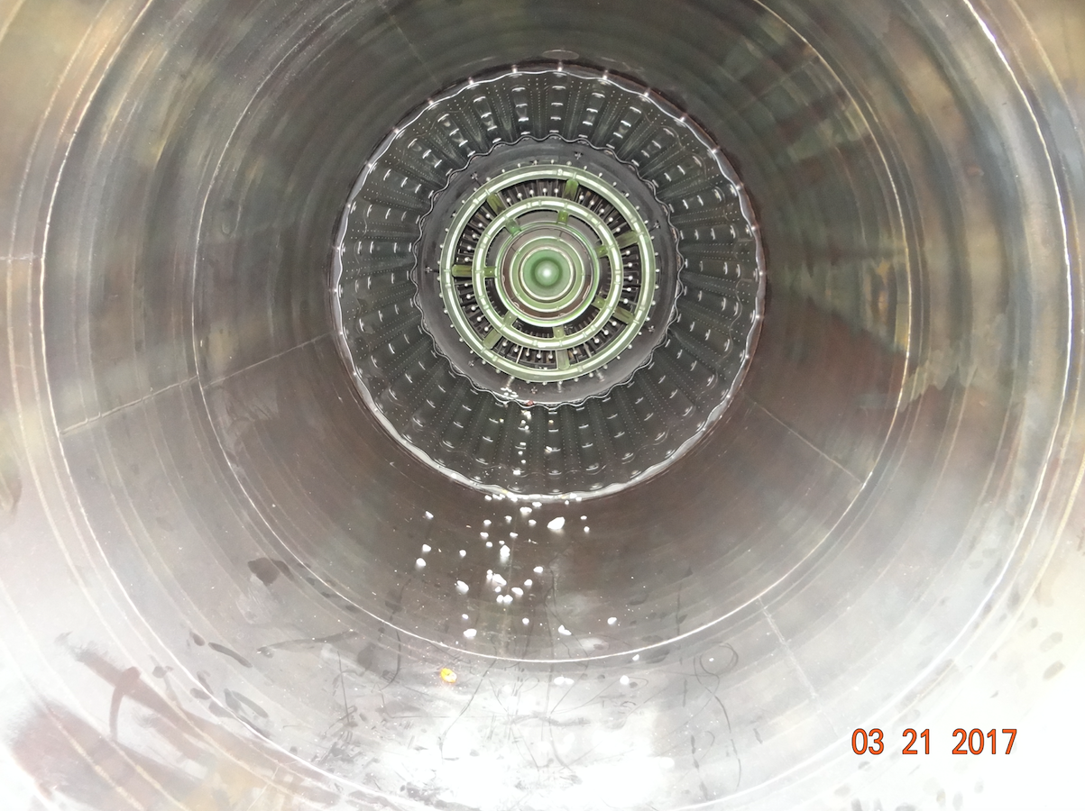
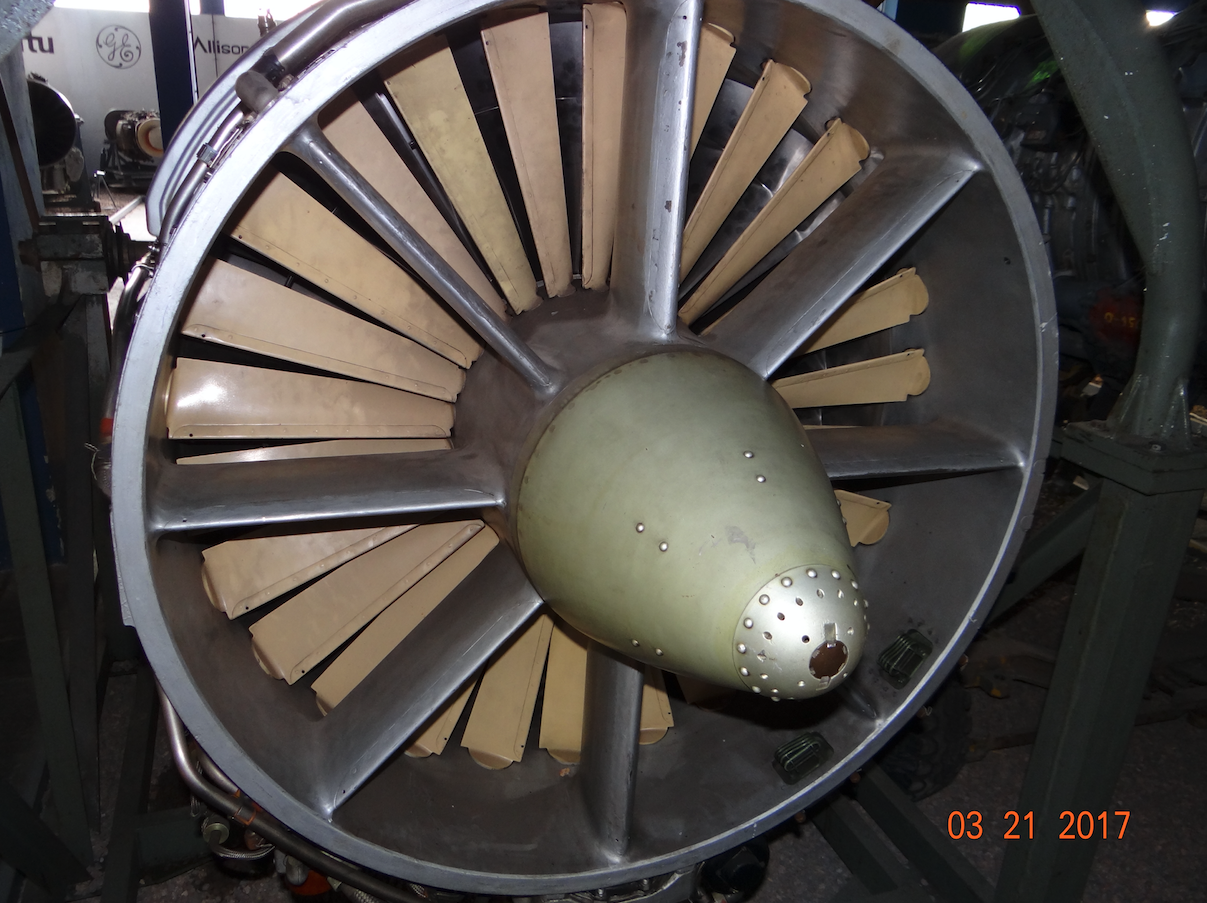
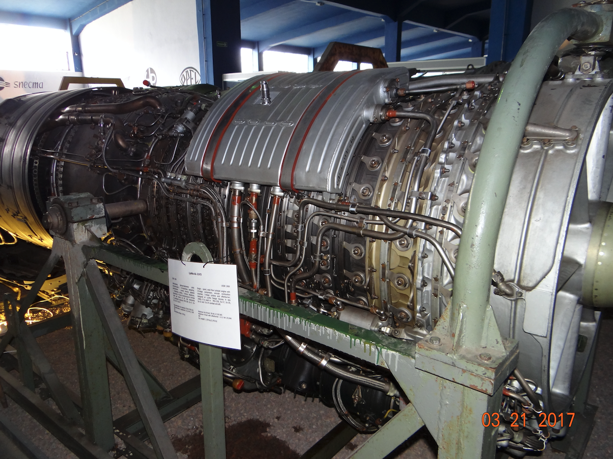
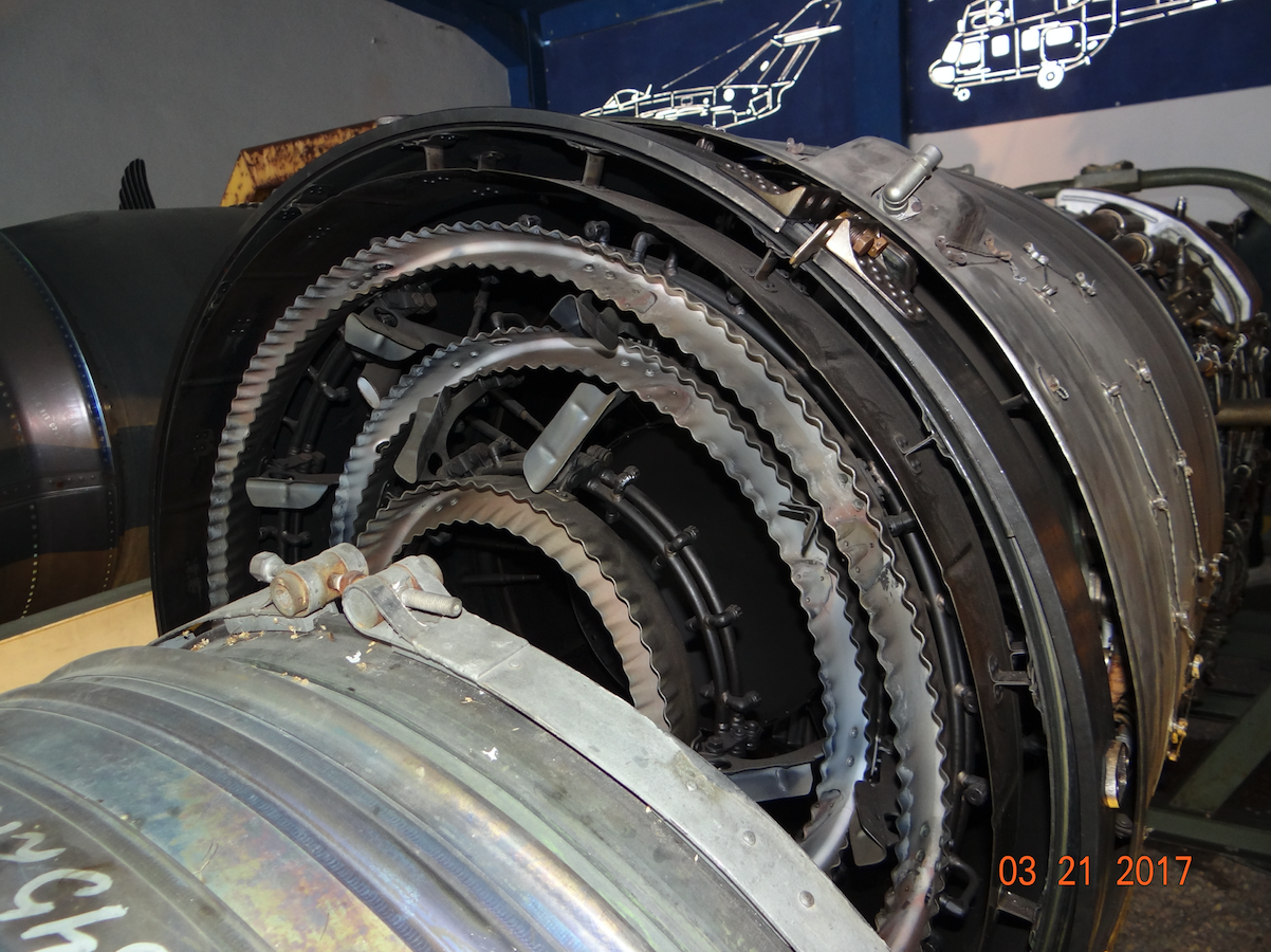
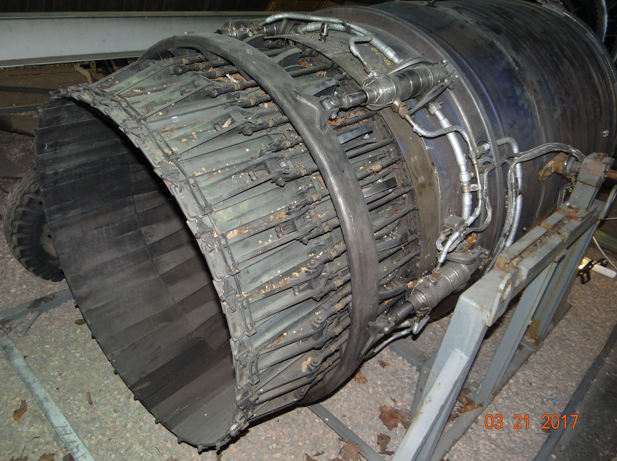
The AL-7 engine is adapted to flights at supersonic speeds. The AL-7 F-1 engine is a single-shaft, single-flow engine with an afterburner. The engine starts with a leading air gush. There are 13 blades in the air inlet which organize the air flow before the first stage of the compressor. The moment a large bird falls into the engine, these steering wheels will cut the bird into smaller pieces which should not cause the engine to stall. There is an axial compressor behind the steering wheels. The compressor is 14 degrees. There are rims between the individual compressor stages. The first rim of the handlebars is adjustable. There is an air bleed downstream of the fifth stage of the compressor which prevents pumping. The compressor pressure is 9.1: 1. The chamber is ring-jug. Fuel injection and ignition takes place in the pitcher. The air flowing around the pitcher cools the pitchers. The turbine is 2-stage. The maximum exhaust gas temperature downstream of the turbine is 685 degrees Celsius. There is an afterburner chamber behind the turbine. The afterburner increases engine thrust by approximately 43%. The engine ends with an adjustable outlet nozzle. The adjustment is made automatically by means of a hydraulic and mechanical system.
Basic data of the AL-7 F-1 engine:
The AL-7 F-1 engine has a maximum thrust without afterburning of 68.65 kN (7,000 kG), and a maximum thrust with afterburning of 98.10 kN (10,000 kG). Engine length 6.81 m. Engine weight 2,395 kg. The compressor pressure is 9.1: 1. The minimum fuel consumption is 0.93 kg / kGxh. Fuel consumption with the afterburner on is 2.3 kg / kGxh.
AL-21 engine.
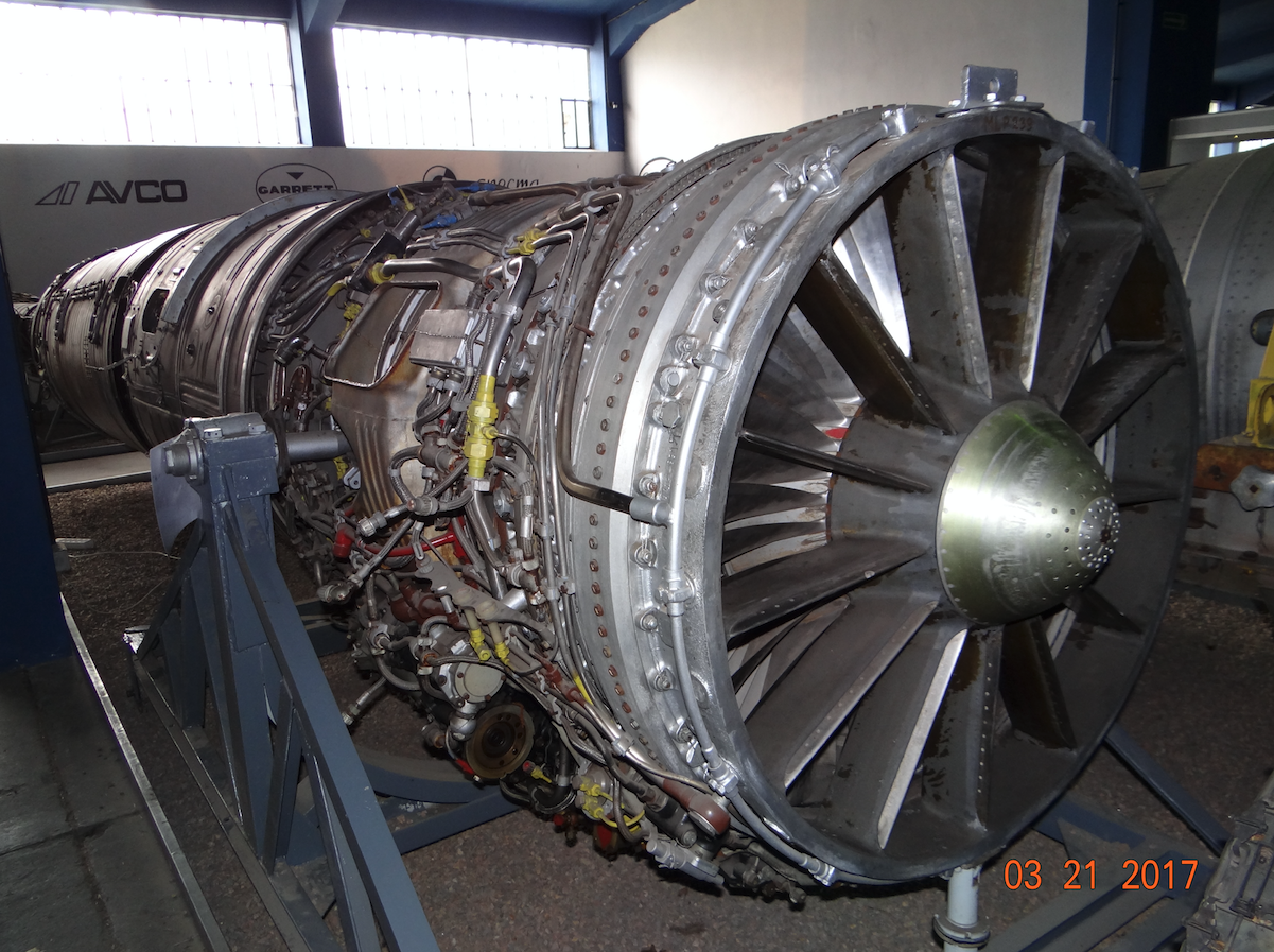
In 60 years, during the Vietnam War, the Russians acquired several copies of the American General Electric J79-GE engine. Like the AL-7 engine, the American engine is single-shaft and single-flow, but has several features that make it better than the Russian engine. The General Electric J79-GE engine is made of heat-resistant metal alloys, which were not present in CCCP. Besides, there is not only one degree of movable steering wheels, but several steps. This solution allows you to fly at supersonic speed while minimizing the risk of pumping. The Russians copied this solution and the AL-21 engine was created. The new alloys allowed for a significant reduction in engine weight. Compared to its predecessor, the AL-21 engine has been specially adapted to flying at low altitudes.
The first launch of the AL-21 engine on the dynamometer took place in 1966. The engine was put into service in 1969. The engine is used on MiG-23 (some versions), MiG-27 (some versions), Su-17, Su-20, Su-22, Su-24 aircraft. The Su-22 planes, depending on the customer’s request, were equipped with an AL-21 or R-29 engine. All Polish Su-22 planes were equipped with AL-21 engines, the same ones that powered the Su-20 planes. Since the 90s of the 20th century, AL-21 engines have been overhauled in Poland in Warsaw.
It is worth mentioning here that in the West, two-flow and two-shaft designs have long been developed. The CCCP continued with simple engines. It was assumed that there was no fuel shortage, which was true and only high engine thrust counts. On the other hand, simple engine designs were easier to manufacture and operate, which was not without significance. However, the effect of such reasoning was the small range of the aircraft, which resulted in a large limitation in the performance of tasks. During the flight, many crews focused on the amount of fuel remaining, rather than on the proper execution of the assigned task.
Construction of the AL-21 engine.
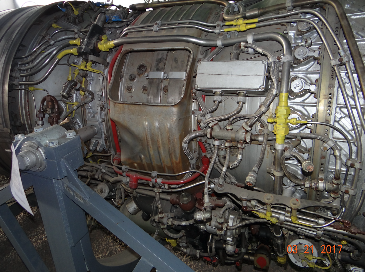
The AL-21 engine is adapted to flights at supersonic speed. The air intake to the engine has a cone that is sharper than in the AL-7 F-1 engine. There are 8 blades in the air inlet which organize the air flow in front of the compressor. Before the first stage of the compressor, there is the first stage of the movable rim. The AL-21 engine has eleven degrees of movable rims. The other steps are stationary. The movement of the steering wheels is carried out by a hydraulic-mechanical system. The axial compressor has 14 degrees. After the seventh stage, there is an air bleed at excessive pressure to prevent pumping. The compressor casing is made of rings that are connected by screws. The combustion chamber is annular. There are 12 fuel injectors in the combustion chamber. The turbine is 3-stage. It is equipped with a cooling system. The engine is equipped with an afterburner. The afterburner is cooled by air taken in by 4 grips located on the fuselage in the rear part. The engine ends with an adjustable gas exhaust nozzle, with a better design than in the AL-7 engine. Adjustment is made by a hydraulic and mechanical system.
The AL-21 engine is lubricated in a closed system. The engine has a BPS-89P installation which prevents the engine from turning off in the air. The engine is started by a TS-21 turbine starter (accelerated with an electric starter).
Basic data of the AL-21 engine:
The maximum thrust without afterburning is 78 kN (7,953 kG). The maximum thrust with afterburning is 111.5 kN (11 369 kG). The engine weight is 1,720 kg.
Kerosene fuel T-1, TS-1, RT. IPM-10 or synthetic WNII-50 oil. Specific fuel consumption 0.9 – 1.2 kg / daNxh, with afterburning 1.5 – 2.0 kg / daNxh. The engine uses 18,000 kg of air for 1,000 kg of fuel. Engine service life is 900 – 1500 hours depending on the production series. Overhaul period of 350 – 450 hours, when some heat-resistant components require replacement.
Written by Karol Placha Hetman

