Kraków 2017-01-02
Aircraft Engines – Ramjet and Pulsejet.
Jet and pulse engine.
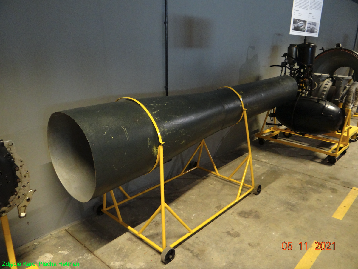
Photo description: The outer casing of the pulse jet engine of the German V1 flying bomb – Fieseler Fi 103.
Argus As 109-014 was the pulse engine that powered the V1 flying bombs. The V1 bomb was a small unmanned aircraft that was automatically controlled by a simple gyroscopic autopilot. The warhead had a mass of 850 kg. Range about 250 km. Cruising speed about 640 km/h. The engine, with a thrust of 2.7 kN (204 kG), was placed above the bomb in its rear part. The V1 bombs were fired from ground launchers set up in northern France. The bomb could be launched from Heinkel He 111 H-22 aircraft. A total of 11,969 V1 bombs were fired.
Ramjet
We will return to history for a moment. In 1908, the French Rene Lorin (1877-1933) theoretically developed and patented the jet engine. However, he could not build a working model, because the aircraft of that time did not have the speed that the jet engine would start working. He presented his theories in the journal L’Aerophile in the period 1908-1913. When another French, Rene Leduc, applied for a patent for a jet engine design in 1933, he discovered these publications. He wanted to contact Rene Lorin, but found out that the latter had recently died.
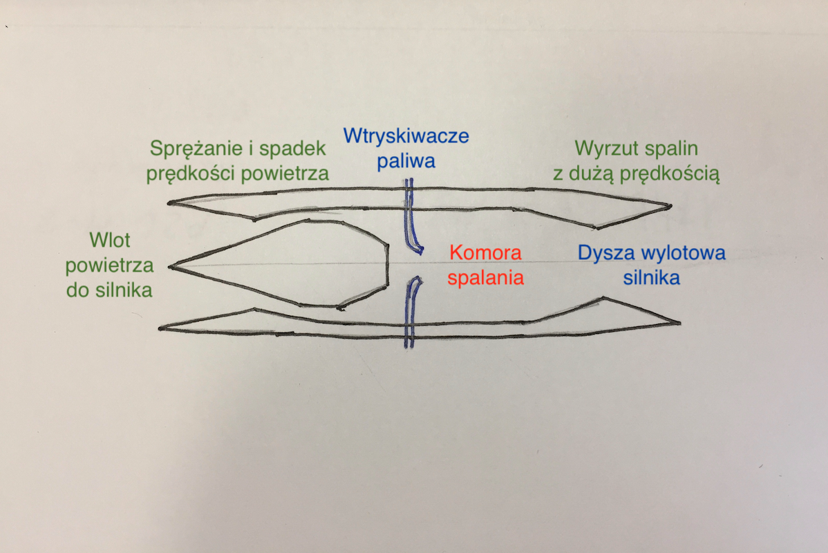
In theory, the jet engine (Ramjet) is very simple, but in fact its thermodynamic operating conditions are more complicated. To date, a fully effective and efficient jet engine has not been developed. Another name for a jet engine is Flying stove pipe or Athodyd (short for air thermodynamic duct). A jet engine is a form of a through-flow engine with no moving parts. This engine uses air compression due to its forward motion. Compressed air receives fuel injection. The air / fuel mixture ignites. The increase in exhaust gas pressure directed through the exhaust nozzle gives the engine thrust. Therefore, this engine cannot provide thrust at zero speed. A vehicle equipped with this type of engine would need a different type of propulsion in order to initiate the motion and combustion processes in the jet engine. In theory, a jet engine would be most efficient in the Ma 3 to Ma 6 speed range. An application for a jet engine is still being sought. There was work with helicopter rotors. Attempts are being made to use jet engines in artillery shells. This type of solution was submitted in 1915 by the Hungarian inventor Albert Fono for the Austro-Hungarian troops. At that time, this idea was rejected.
We mentioned the difficult thermodynamic operating conditions of the jet engine. Such an engine must be designed for a specific speed range, as its efficiency decreases with increasing speed. This is because the inlet air temperature increases due to greater compression. As the inlet temperature approaches the outlet temperature, a smaller proportion of the energy can be extracted as a string. In order to create the necessary engine thrust, this air should not be compressed so much so as not to raise the temperature. This means that the flow through the engine will be supersonic, and all modern turbojets have subsonic flow, even though the plane is flying at Ma 2 – Ma 3. This undesirable increase in temperature at the moment of compression immediately necessitates an intercooler.
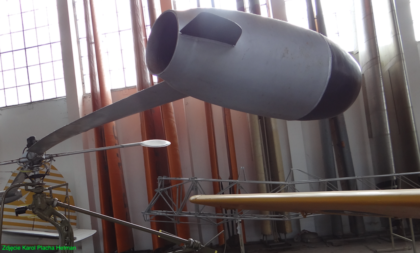
Russians performed many tests with jet engines at the turn of the 30s and 40s. However, little information is left about these works. They used DM-1 and DM-2 jet engines as additional engines in the I-15 and Jak-7 airplanes.
French experiences.
Rene Leduc (1898-1968) was the most successful with the jet drive (ramjet). Rene Leduc was a French engineer who started working on jet engines in 1938, and in 1949, he created the world’s first jet powered airplane – the Leduc 010. Eng. Rene Leduc worked at Breguet Aviation. In 1938, he set about developing an airplane powered solely by a jet engine. During World War II, the plants operated for German needs. Work on the plane slowed down. As a result, the Leduc 010 plane was not ready until 1947. Two prototypes were built. The entire fuselage of the airframe was practically an engine. The crew was placed in a separate cabin located centrally in the front part of the fuselage. Thus, the intake to the engine was annular. The plane had a length of 10.25 m, a span of 10.52 m, a curb weight of 1,700 kg, a take-off weight of 2,800 kg, and an engine thrust of 15.7 kN. Tests began in Toulouse in October 1947. The loss of the Leduc 010 aircraft was carried out with the carrier aircraft Sud-Est SE.161 Languedoc. The first engine flight was made on April 21, 1949. The tests achieved a speed of Ma 0.85, a ceiling of 11,000 m (36,000 ft) and a climb speed of 40 m / s. These were very good results. Both Leduc 010 prototypes were lost in accidents where pilots survived with multiple injuries.
Work on the program has not stopped. Another prototype of the Leduc 011 was created, which had small turbojet engines at the wingtips to ensure a self-launch. The first flight was made on February 8, 1951. However, there were problems with the plane and turbo-jets were abandoned.
The program continued. In 1953, two more prototypes, designated Leduc 021, were built. The planes were 30% larger than the Leduc 010. Span 11.60 m, length 12.50 m, curb weight 3,300 kg, take-off weight 6,000 kg, jet engine (ramjet ) with a thrust of 63.7 kN. The tests took place in the period 1953-1956. The tests covered 284 flights. The plane reached the maximum speed of Ma 0.95, and that was not enough in the mid-50s. The design was not suitable for supersonic flights. Therefore, one more Leduc 022 plane was created.
The Leduc 022 aircraft was intended for supersonic flights in the Ma 2 speed range. It was built as a prototype of a fighter aircraft. It was an attempt to apply the jet engine technique in practice. Unlike its predecessors, it received oblique wings. The power unit was a jet engine (ramjet) and turbojet engine. The idea was for the plane to take off independently. Leduc 022 was 18.21 m long, span 9.95 m, curb weight 6,380 kg, take-off weight 9,000 kg, jet engine with 63.7 kN thrust, Snecma Atar 101D-3 turbojet, with 31.4 kN thrust. The first flight was made on December 26, 1956. During the tests, it was not possible to exceed the speed of sound due to the significant induced airframe resistance. The program ended in 1958 for the further development of the Dassault Mirage III aircraft.
The French have developed another project of an aircraft powered by a ramjet. It was a plane from the Nord Aviation Nord 1500 Griffon (Sęp) company. It was an aircraft that was to meet the French requirements for a combat aircraft reaching Ma 2 speed. The aerodynamic system was from the late 40s and was based on delta wings supplemented by small wings in the front part of the fuselage. The plane was to operate from a ground take-off field (grass) and had a 1,000 m take-off run. The powerplant was to be mixed: a turbojet engine supported by a jet engine. Two prototypes were built.
Only the Atar 101 turbojet engine was used in the first prototype. Nevertheless, the Griffon I aircraft accelerated to Ma 1.17. The Griffon II prototype was equipped with a target power unit. The first flight was made on January 23, 1957. The speed of Ma 2.19 (2,330 km / h) was achieved in the tests. overall the construction was a success. However, there were some significant drawbacks. The airframe was getting very hot in the area of the working jet engine. The designers did not have titanium or inconel (an alloy of nickel, chromium and iron). Besides, the plane could fly either very fast or at subsonic speeds. Turning on the jet engine caused a rapid increase in speed, and turning it off caused instant braking up to 900 km / h. The company proposed the Super Griffon version. But the program was closed due to the much simpler Mirage III plane.
Griffon II: length 14.54 m, span 8.10 m, weight 6,750 kg. Atar 101 engine with 34.3 kN and Nord Stato-Reacteur streamer with 68.0 kN.
The epilogue of ramjet engines.
Contrary to popular belief, the internal shape of a jet engine is very complicated. Most of these engines operate at supersonic flight speeds. That is why the inlets are equipped with elements which generate oblique or conical shock waves. They cause the air velocity to fall to subsonic velocities and its compression. Further diffusion brings the air flow velocity to a value suitable for a stable fuel combustion level. It turned out that this type of engine is very sensitive to the swirls made by the plane, because the angle of the airflow changes, and there are no aerodynamic blades to organize the air.
Subsonic thrusters do not need such sophisticated gaps because air enters the engine at a slower speed.
As in other flow engines, the operation of the combustion chamber consists in creating an air-fuel mixture and its ignition at a constant pressure. The combustion should be stable and the flames should not extend beyond the combustion chamber. The entire combustion reaction must take place in the combustion chamber in order to obtain the maximum pressure increase. Since there is no turbine downstream of the combustion chamber, the jet engine can operate at the maximum temperature of the combusted fuel. For kerosene (kerosene) it is 2,130 degrees C. After the combustion chamber there is usually a diffuser, followed by a confusor. At subsonic speeds, a diffuser is sufficient.
Tests have shown that the engine does not run uniformly, not only in varying speed ranges, but also depending on the ceiling and outside temperature. In general, each engine has its own narrow range of the most favorable speed and flight altitude. Therefore, every now and then the idea of propelling transport planes with such a propulsion is revived, because they usually fly at a constant speed and at similar nominal altitudes and do not make complicated turns.
Although it has been possible to create jet engines operating at a forward speed of 160 km / h, they are ineffective due to insufficient compression pressure. Good results are only achieved at a speed of Ma 0.5 (about 610 km / h).
Problems with engine control also appeared. When the engine starts to run on its own, the airplane tends to accelerate steadily. At the same time, the temperature at the inlet and outlet increases, which typically increases the temperature of the engine and airframe. You can destroy the engine. Therefore, the amount of fuel fed is included, which brings about a thermodynamic equilibrium. The aircraft will stabilize the speed and thus the inlet and outlet temperature at a reasonable level.
Jet engines have one more feature. Combustion in it is stoichiometric. (For kerosene it is 15.0. For gasoline 14.9.). Therefore, their performance at Ma 2-3 speeds is good. However, at low speeds, they fail to turbojet and even rocket engines.
Jet engines have found wide application in missile propulsion. Typically, a mixed rocket and jet propulsion is used. The rocket engine gives the missile an initial velocity, and the jet engine maintains this velocity.
The great advantage of the jet engine is its simple structure. No moving engine parts. Thanks to this, such an engine is cheap to produce and operate. Modern jet engines are also very durable.
Pulsejet.
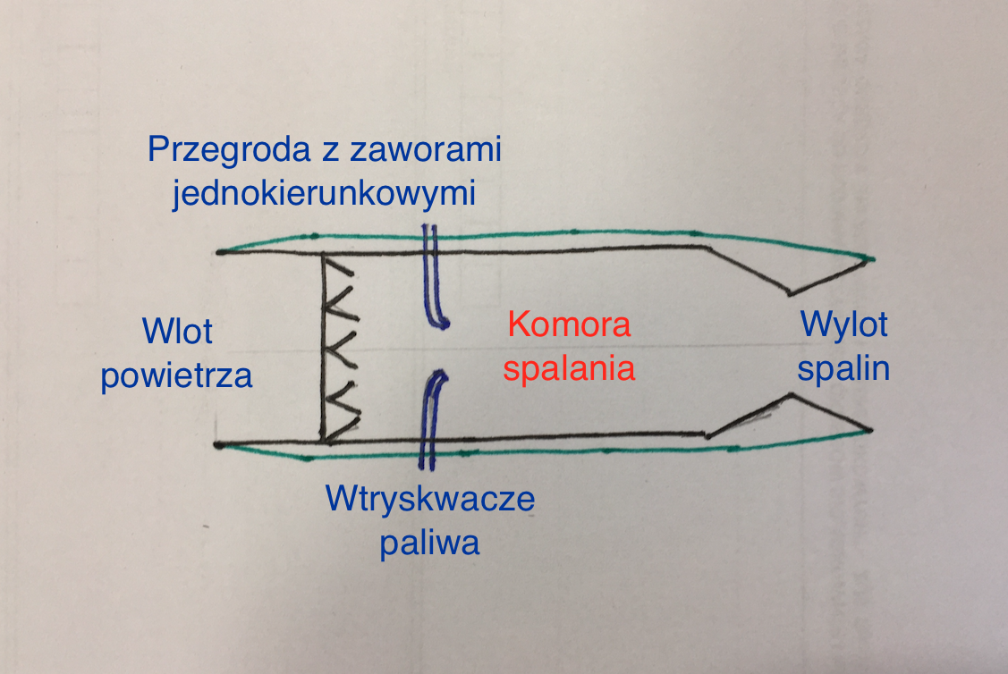
The pulse engine became the development of the jet engine. The pulsejet is a variation of the jet engine. It consists of an air inlet, a non-return valve system, a combustion chamber and an outlet nozzle. The most famous example of a pulse engine was the propulsion unit of the Fieseler Fi-103 winged bomb, better known as the V-1 and used in combat by German troops during the Second World War.
How does the pulse motor work? A portion of the oxidant (air) enters the engine through the air intake, into which the fuel is injected and ignited. The ignited mixture increases the pressure causing the check valve system to close. The exhaust gases can only flow into the exhaust pipe and exhaust nozzle to provide engine thrust. A suitably long exhaust pipe creates a negative pressure in the combustion chamber, which will allow another portion of air (oxidant) to be injected and the cycle repeats itself. Initially, the mixture is ignited with a spark plug. Ignition occurs automatically when the engine is warmed up.
Pulse engines have a relatively low thrust and are therefore suitable for propulsion of small aircraft. The advantage of the pulse motor is its simple structure and simple operation. Additionally, the engine does not require the use of thermally high-resistant materials, as the engine operating temperature is similar to that of a piston engine. However, the engine generates significant noise and strong vibrations, therefore it is not suitable for propulsion of piloted aircraft. The big problem is forcing the ignited mixture to move towards the rear to provide thrust, and not in the opposite direction, i.e. the air intake. Therefore, shutters and windows that open in a timely manner in the side walls of the channel can be used. Also for this reason, the inlet channel may be U-shaped open at both ends. In any system, the big problem is to remove the entire burnt portion of the mixture. If the mixture does not burn completely, it will burn outside the engine, which is disadvantageous.
Written by Karol Placha Hetman


